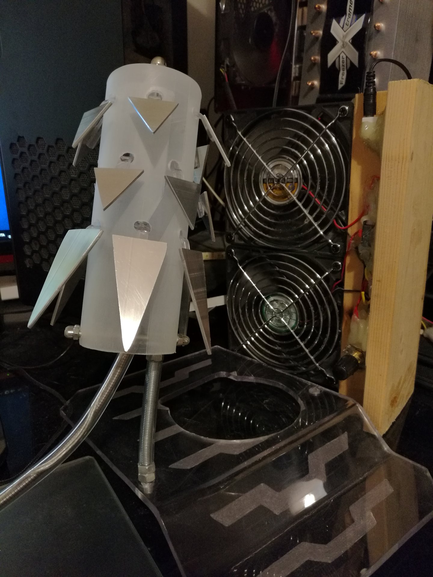
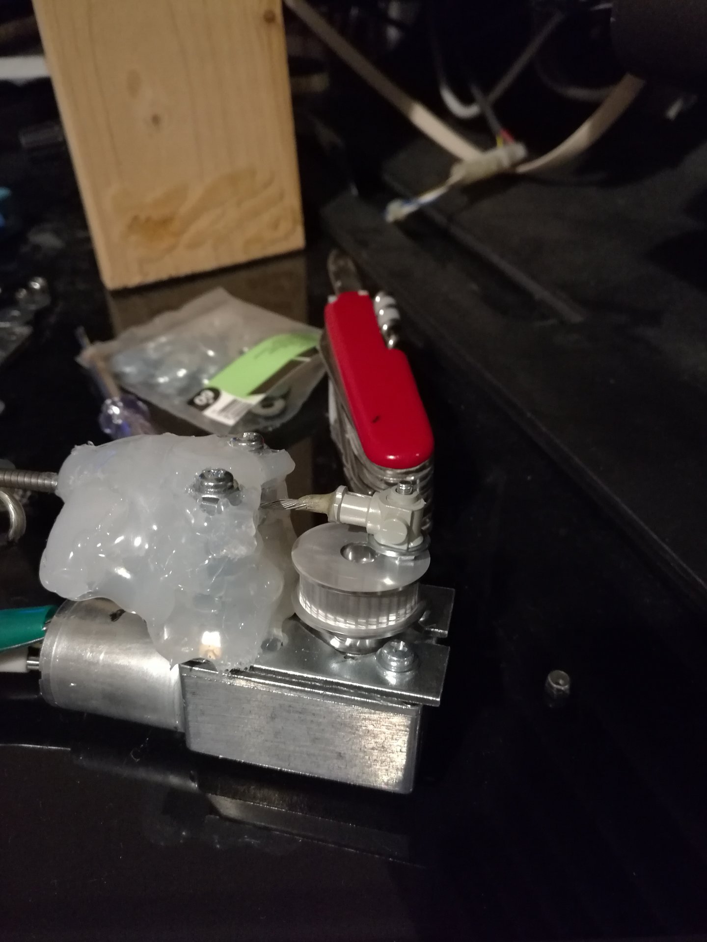
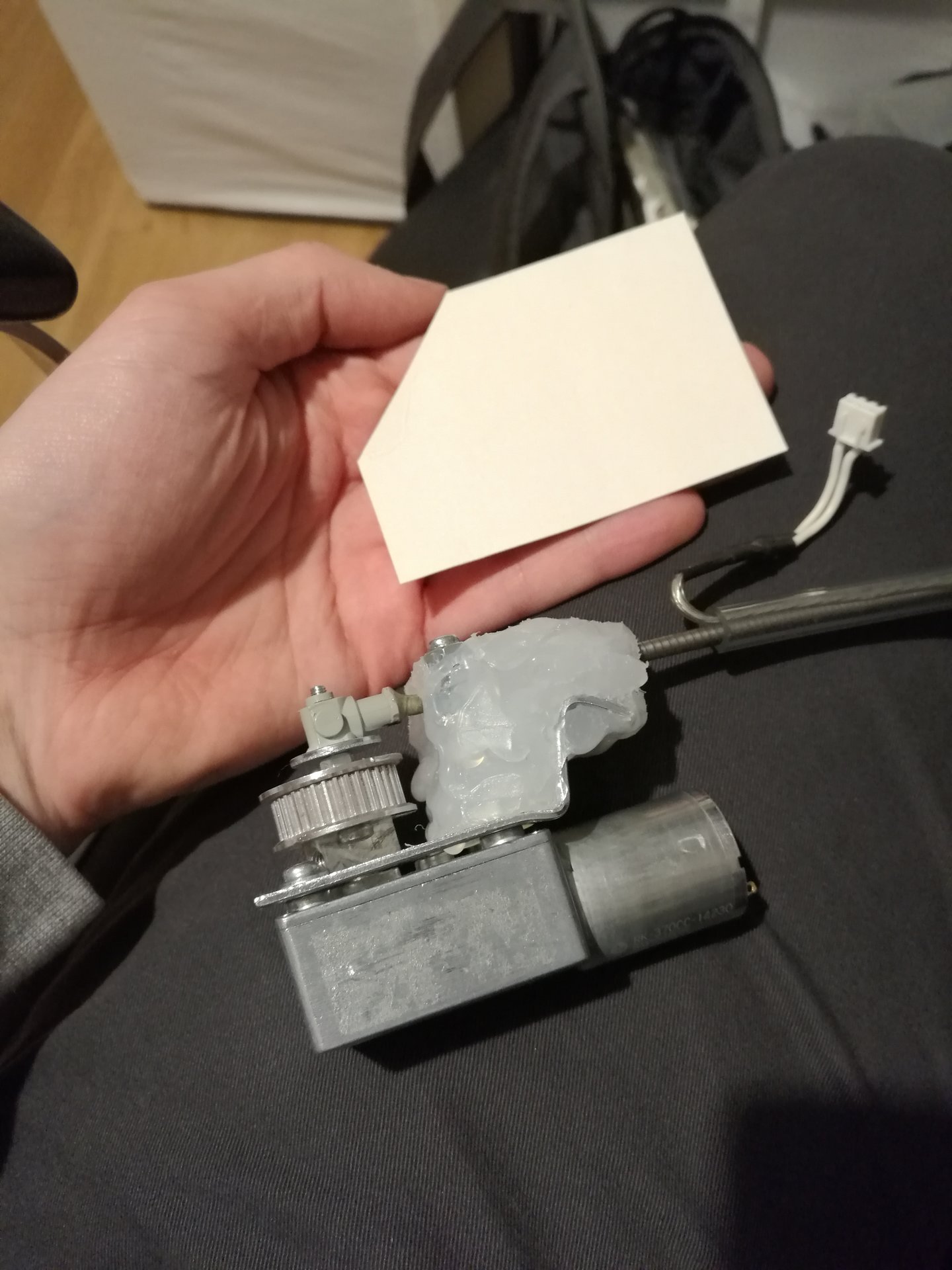
The first upgrade I have done is to the motor of the prankster bit, because the old Lego motor had a lot of problems: it was too much noisy, big and weak, and the plastic gears were fragile (I broke and replaced some of them in the years).
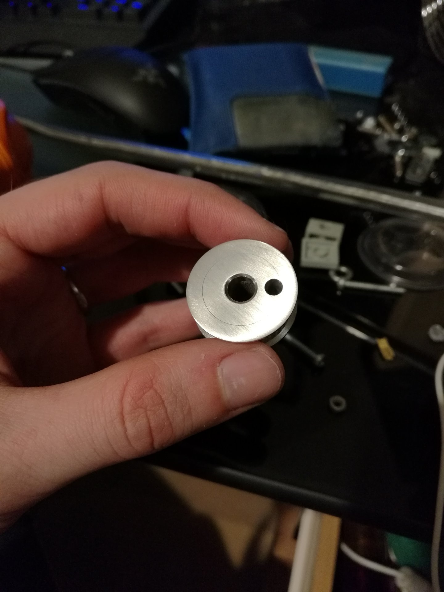
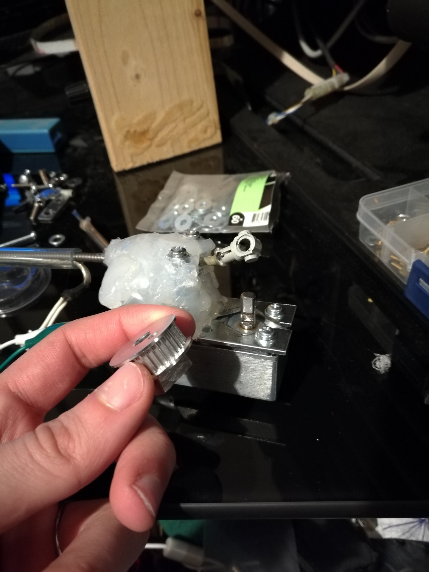
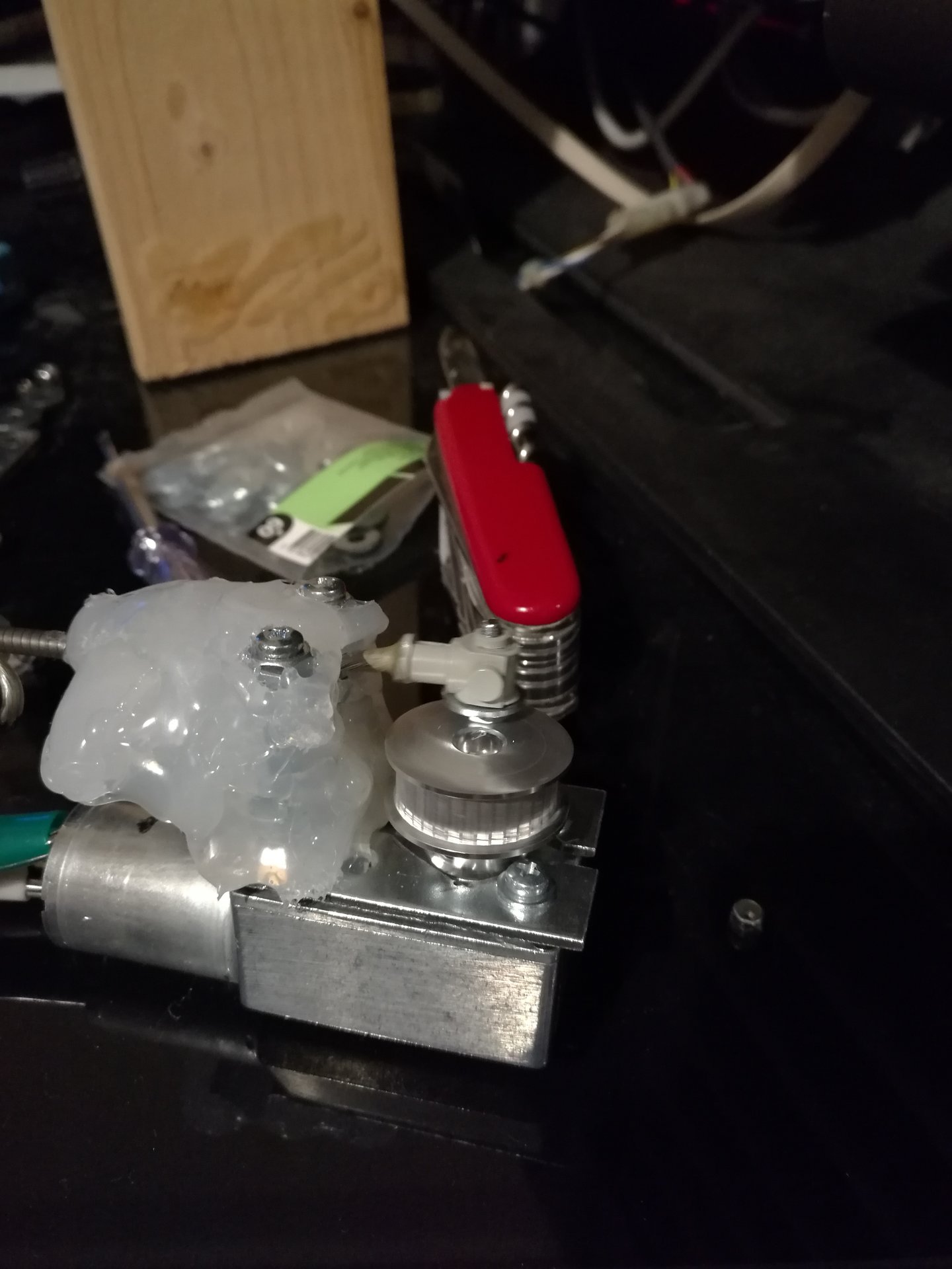
So I replaced it with an electric motor with integrated reduction gears, that rotates slowly at 20 rpm. I mounted on it an aluminum pulley in which I have drilled an eccentric hole to mount the brake cable:
This is a video of the new motor in action, while moving the Prankster bit :
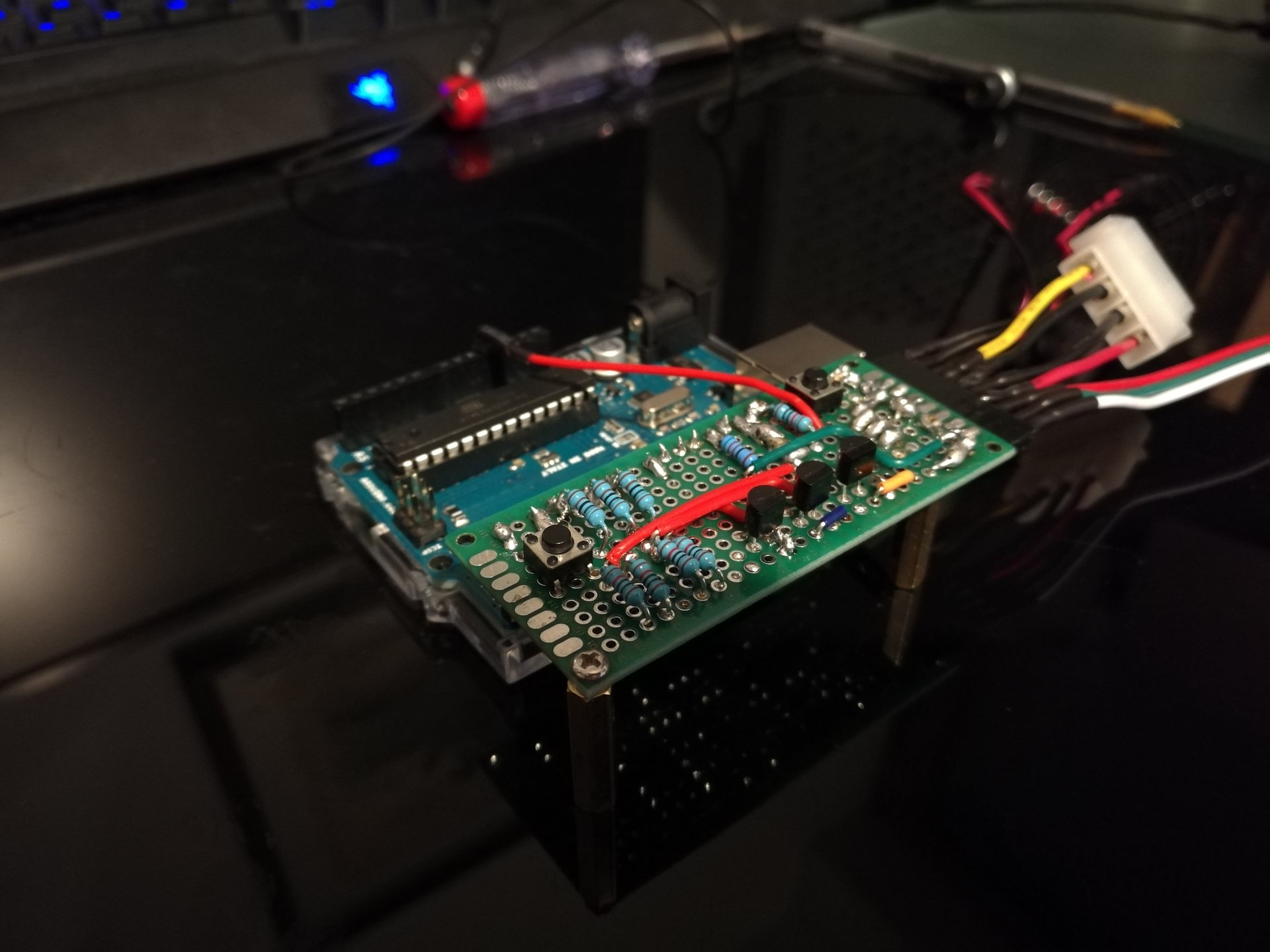
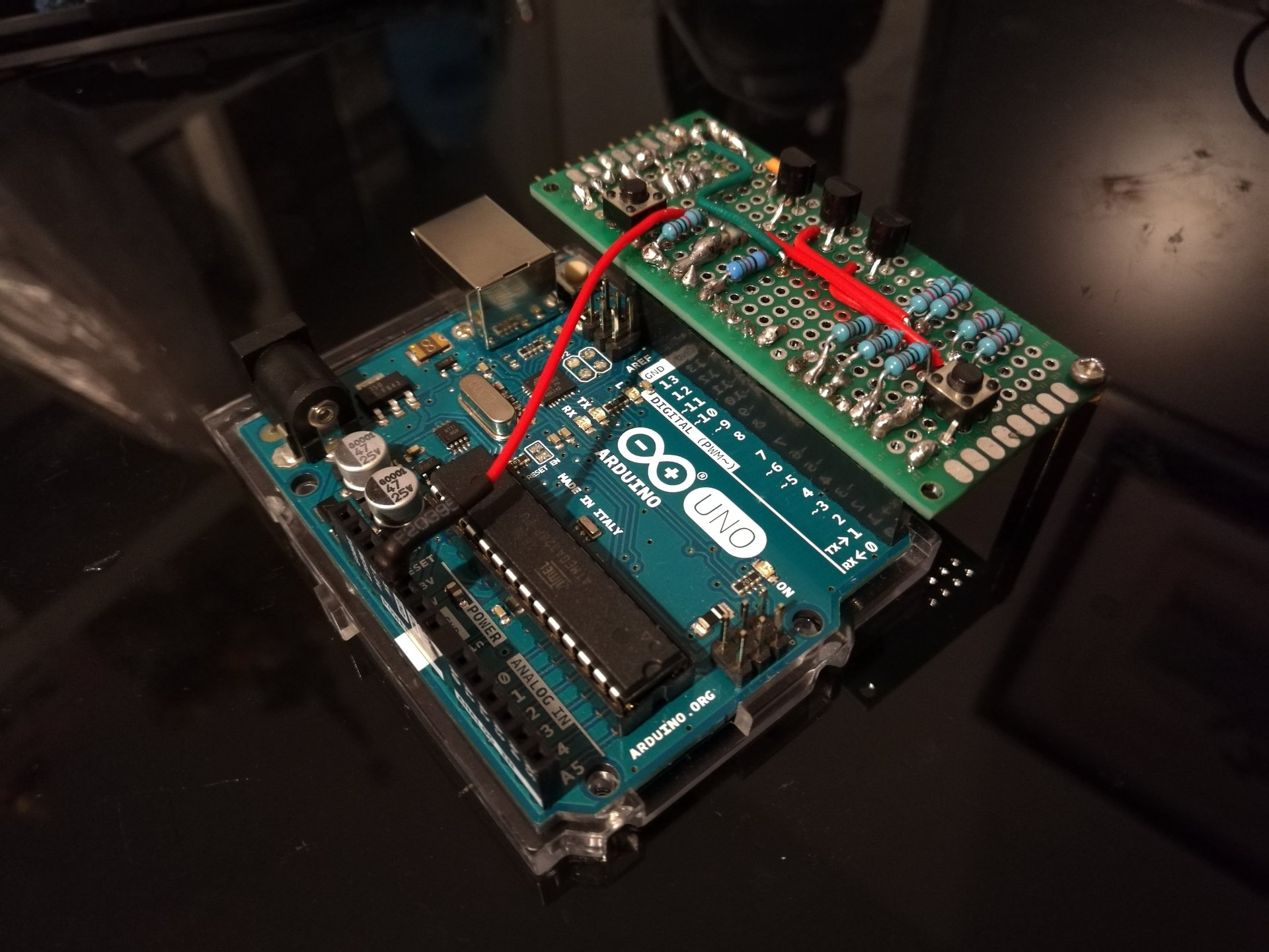
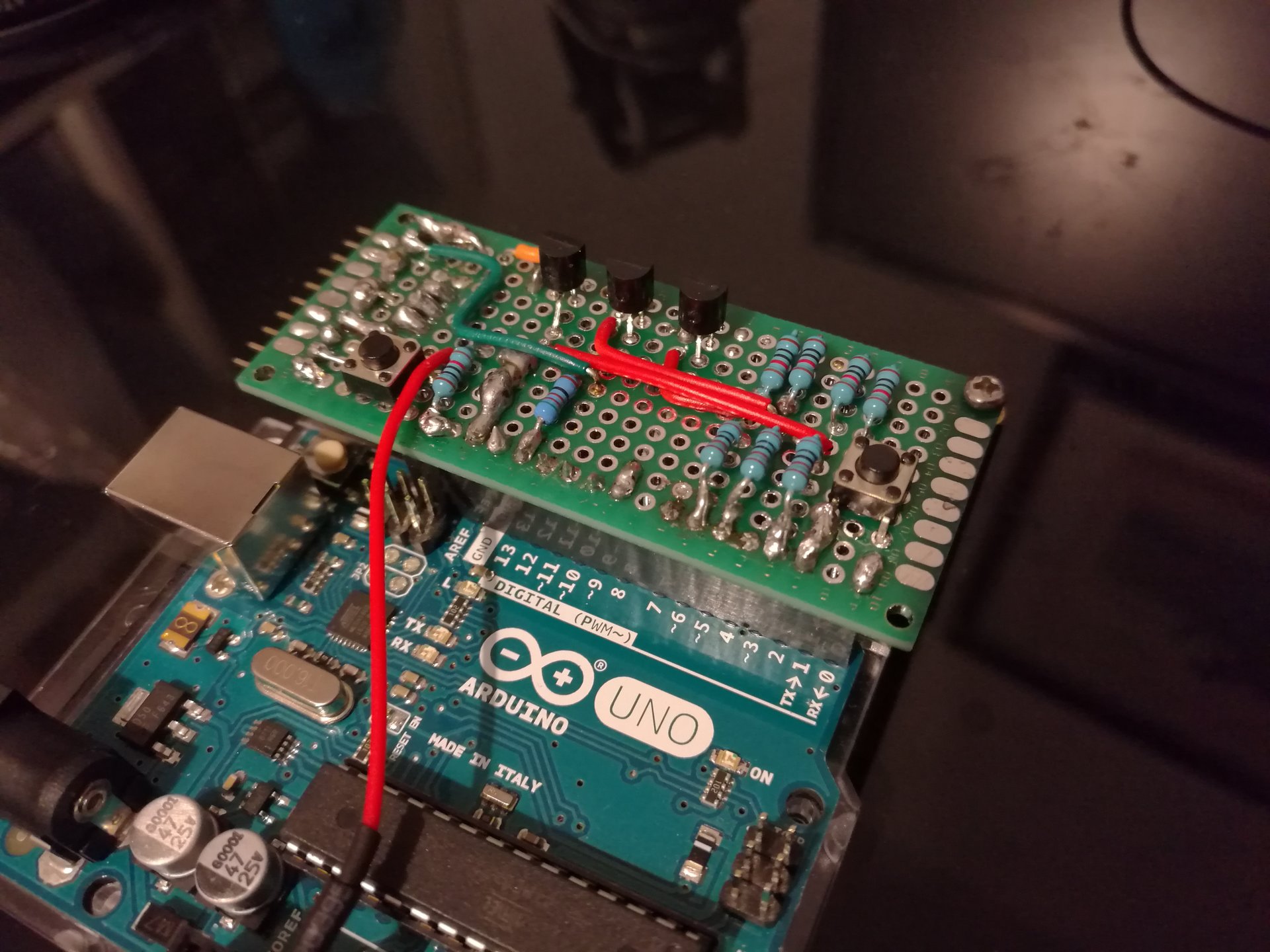
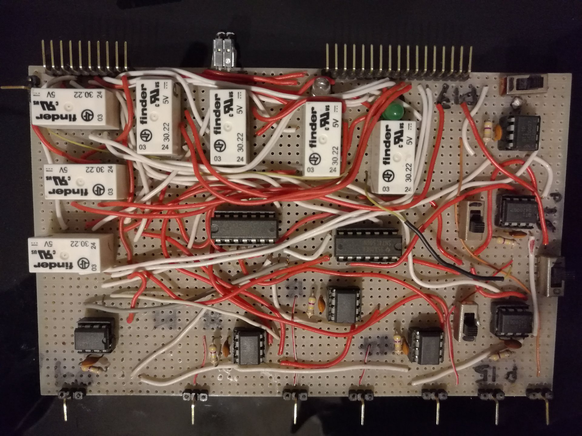
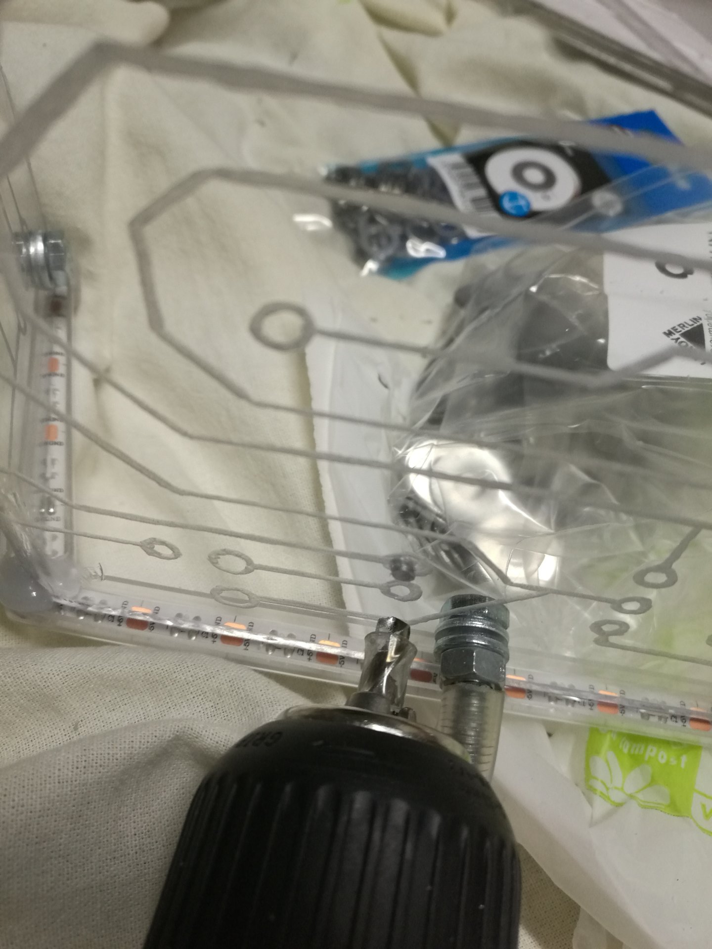
I have completed the circuit for Arduino, adding a second button (to be connected to a touch sensor). I have added these little buttons on the circuit to testing it without connecting the actual touch sensors.
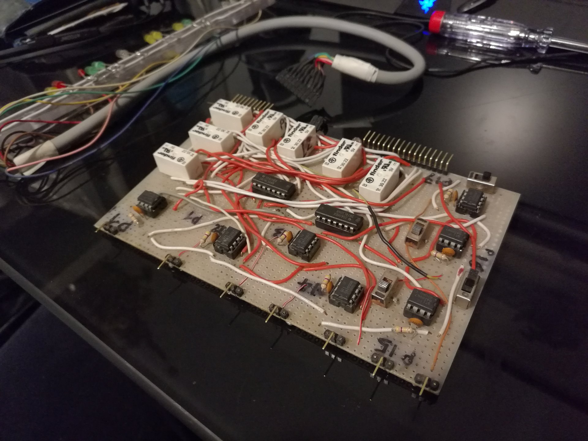
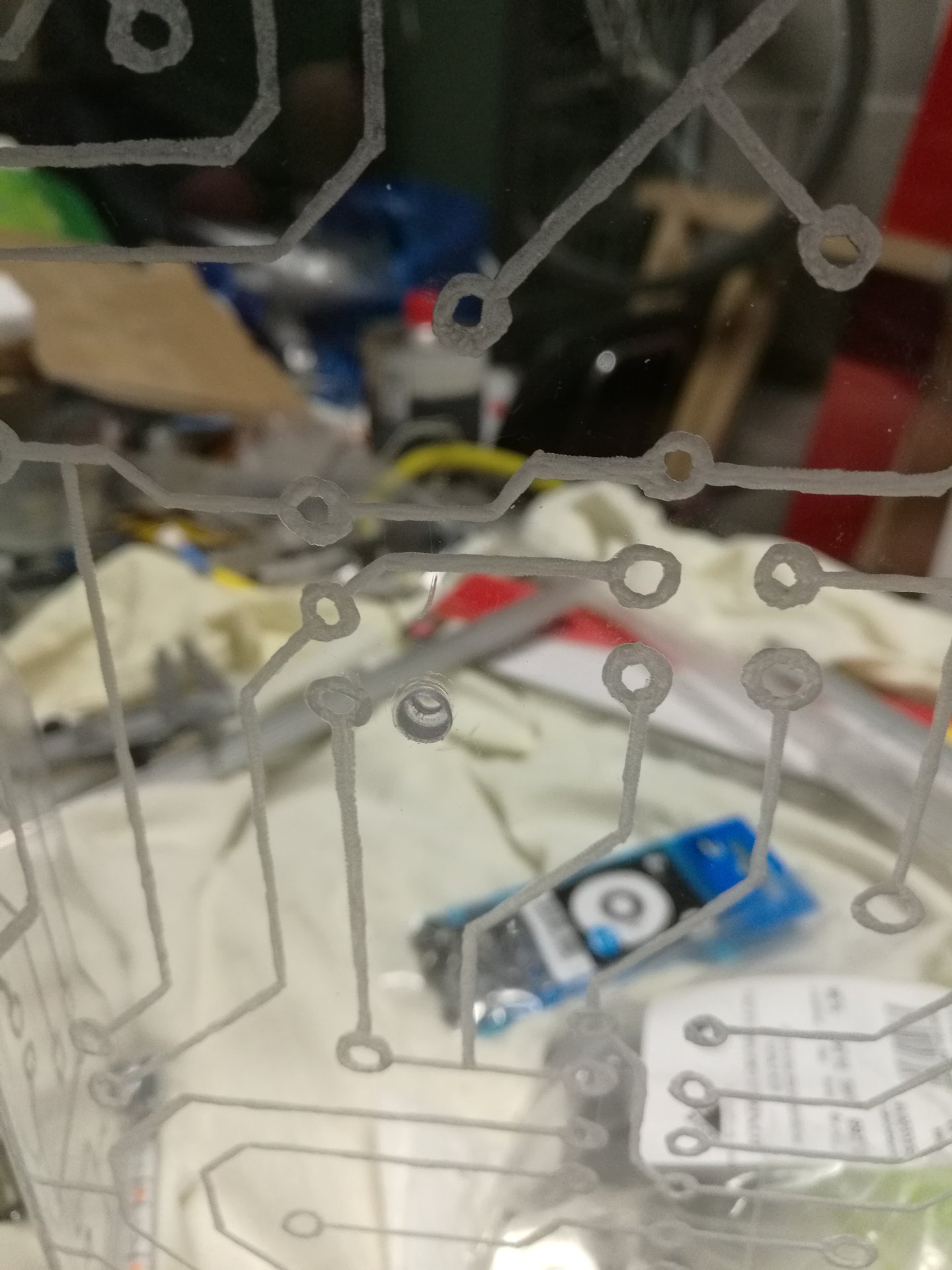
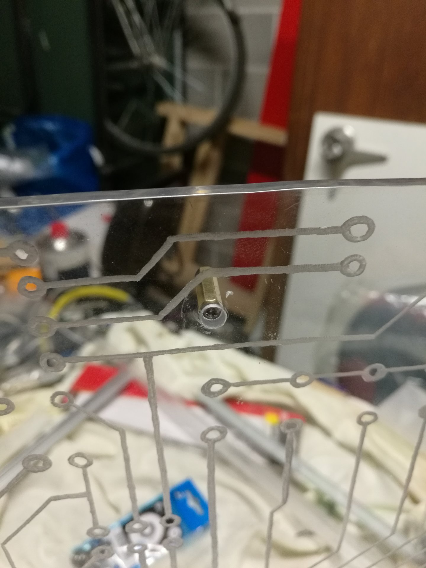
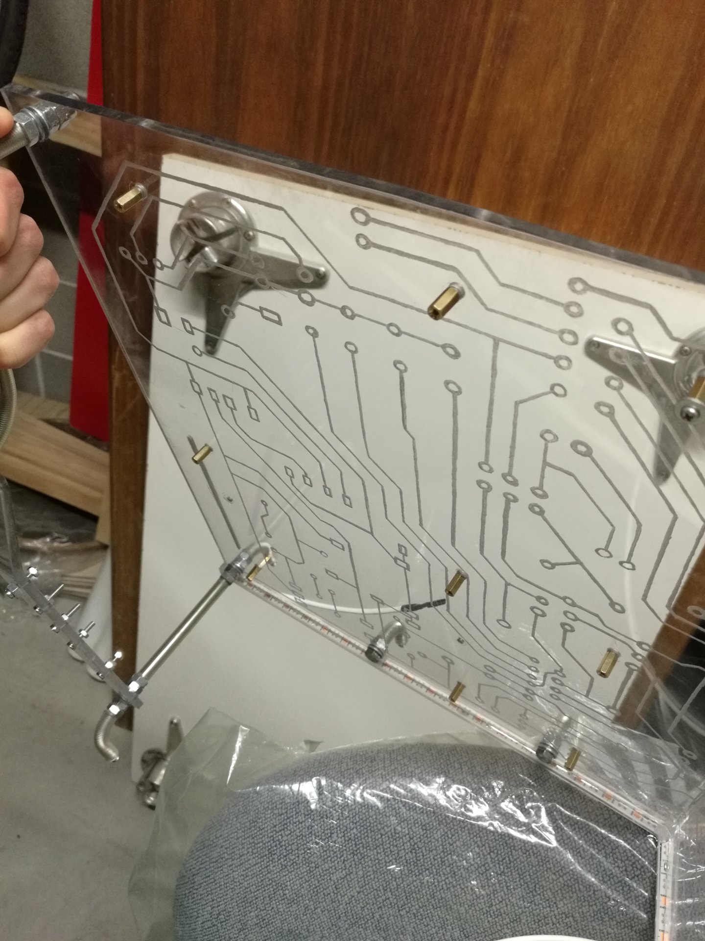
Then I have done some changes to the old sensors circuit, to adapt it to the new configuration:
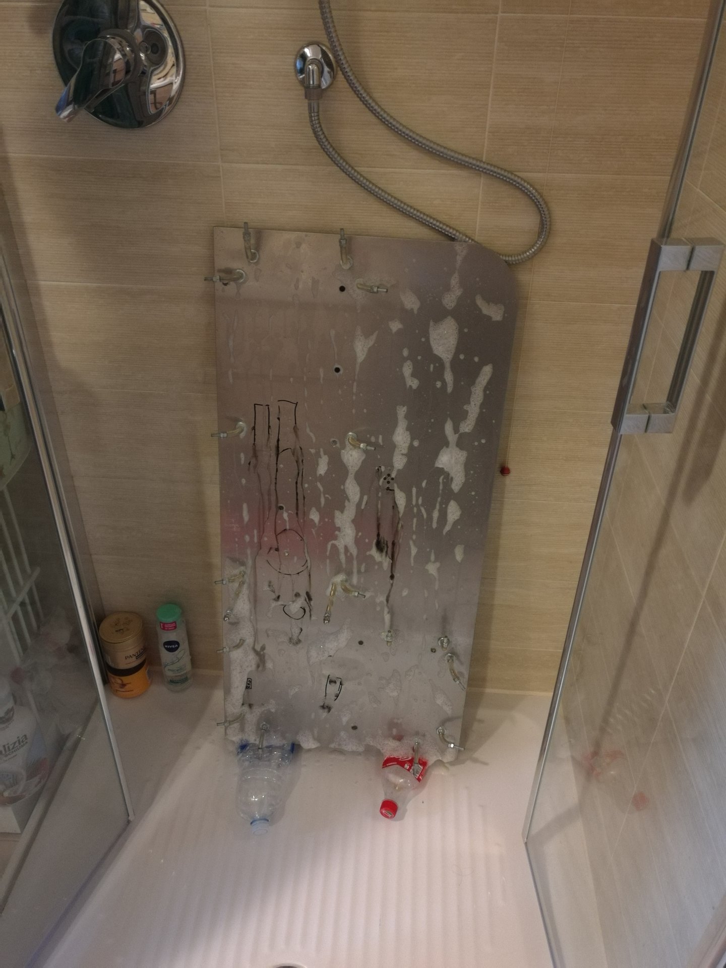
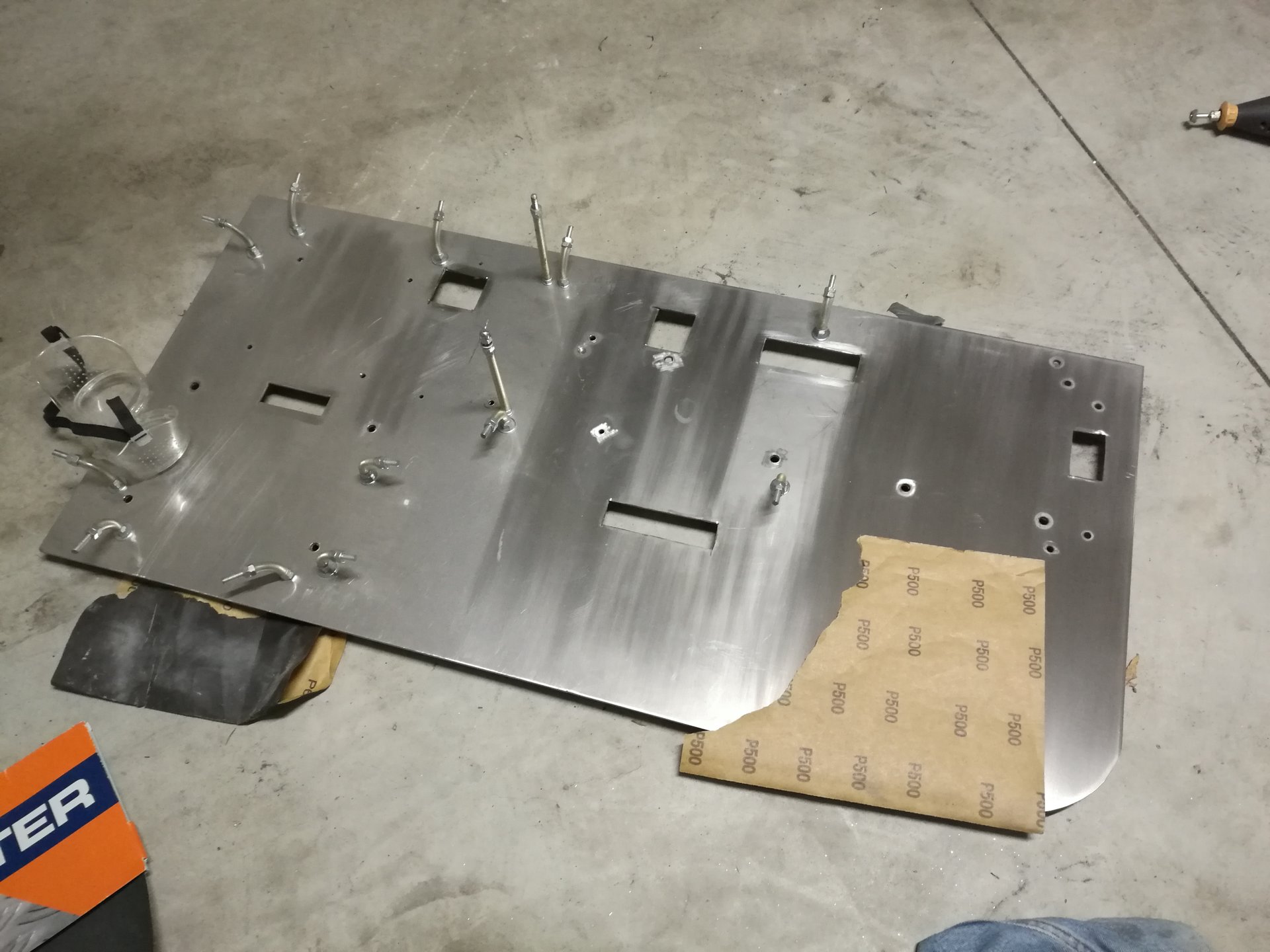
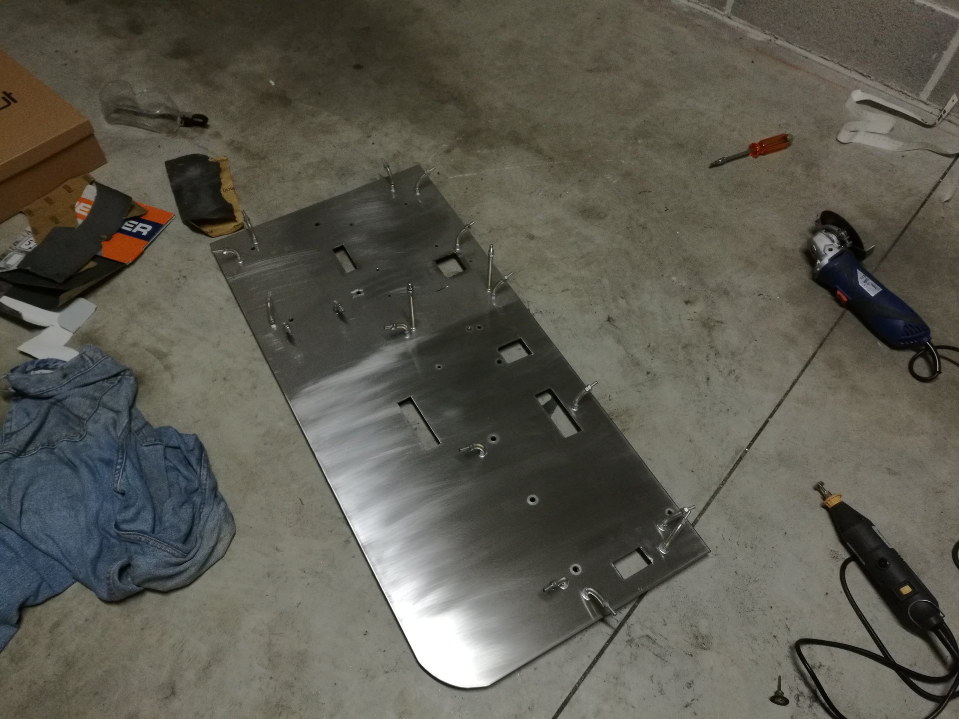
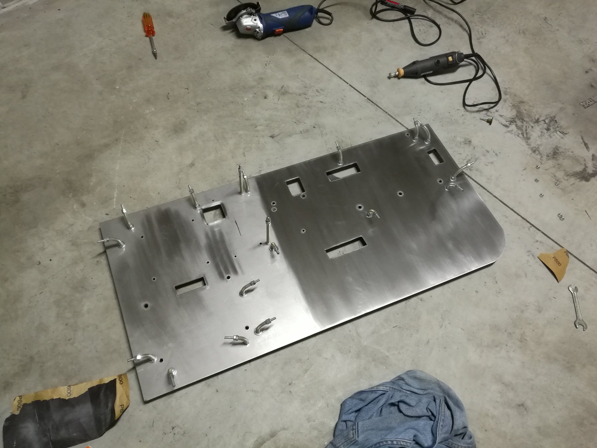
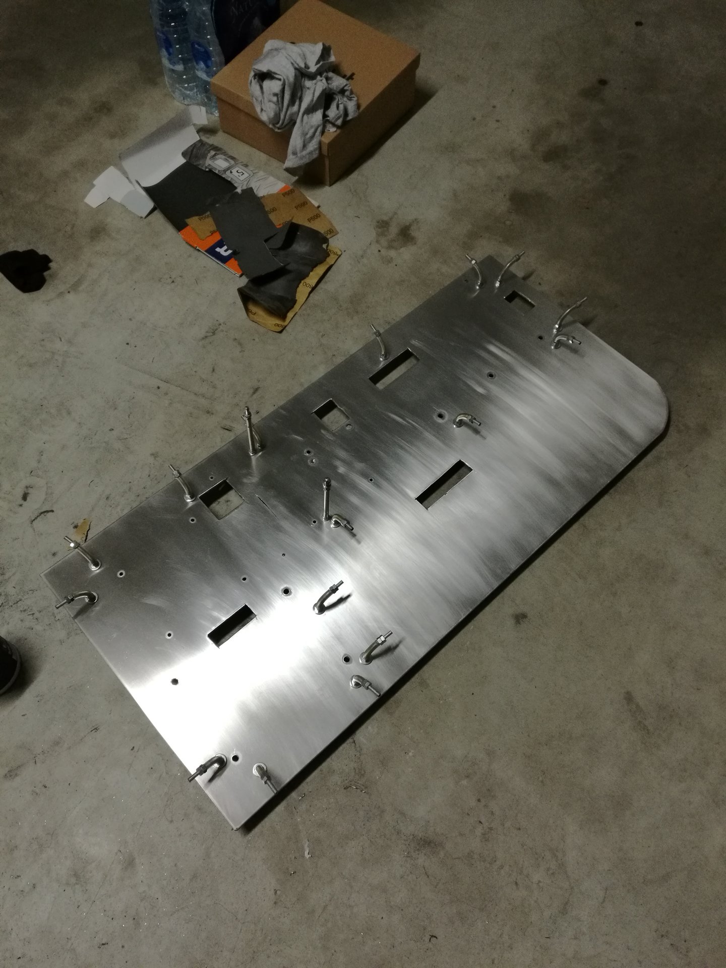
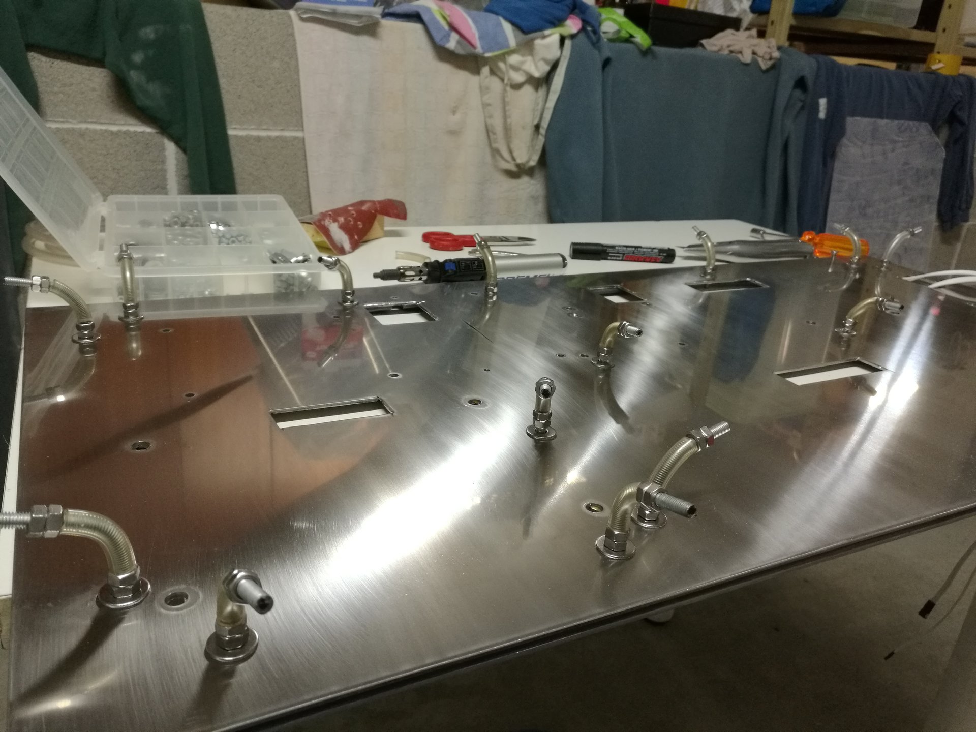
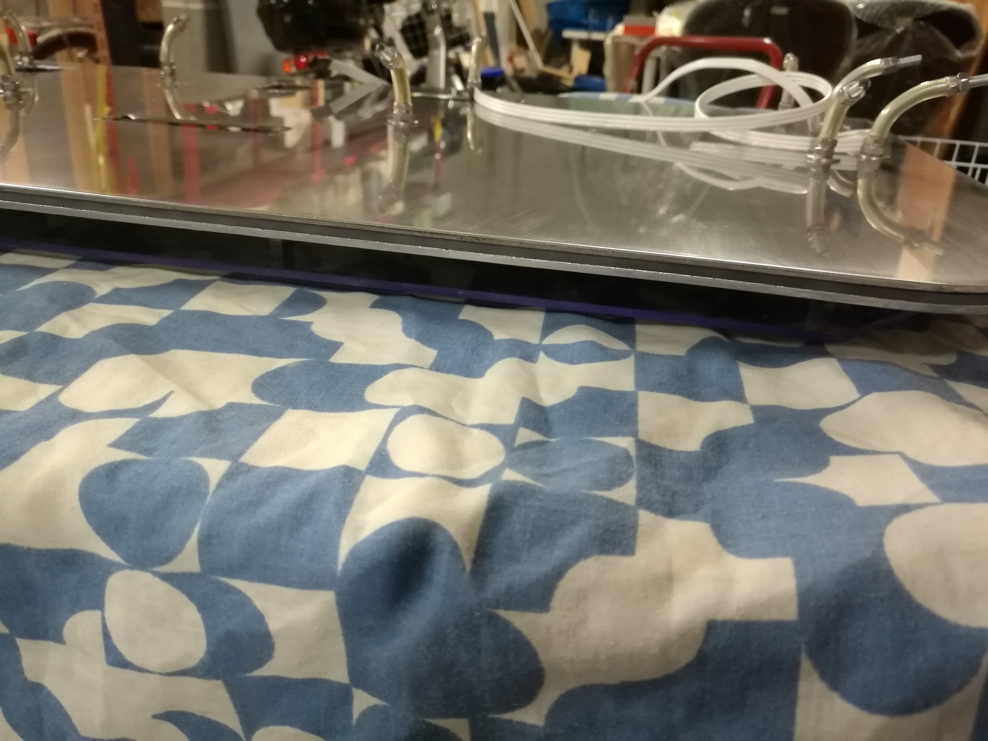
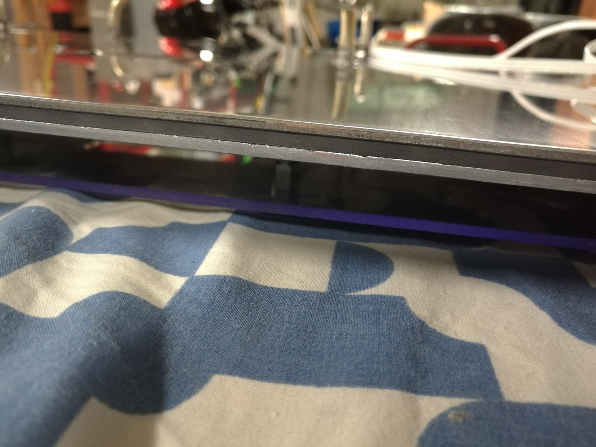
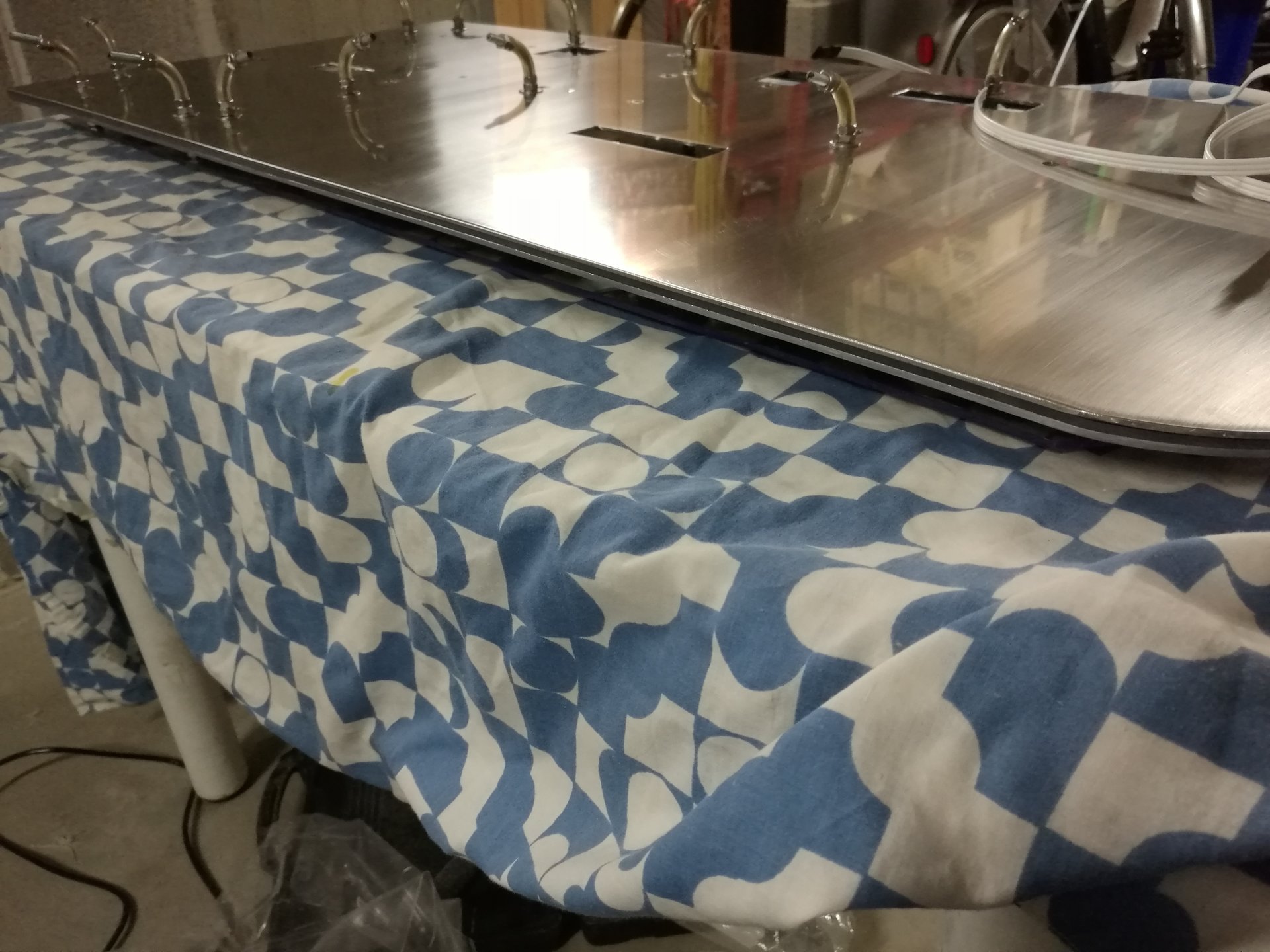
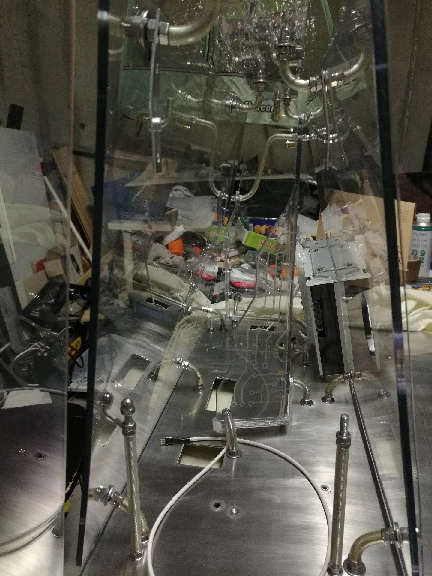
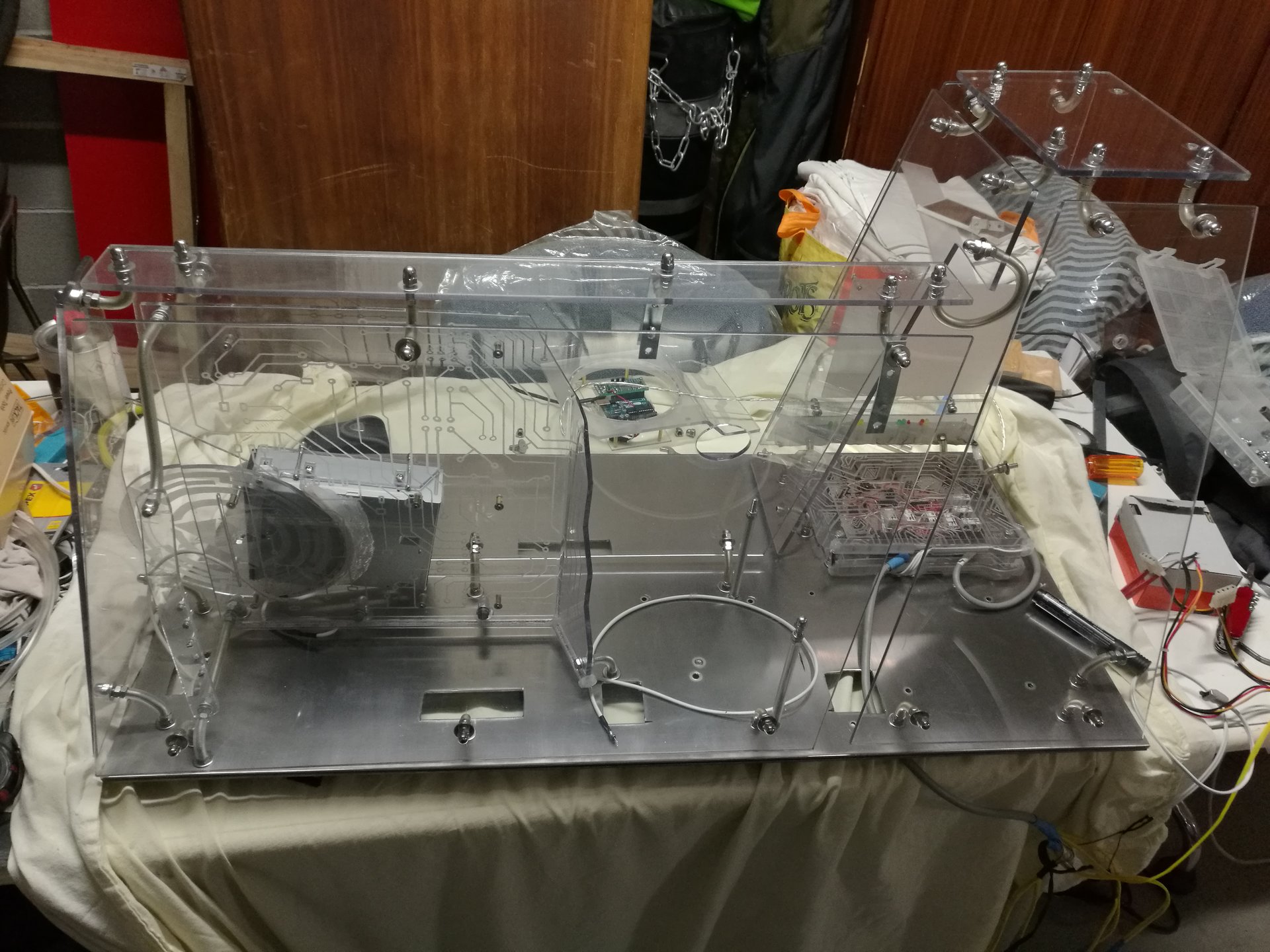
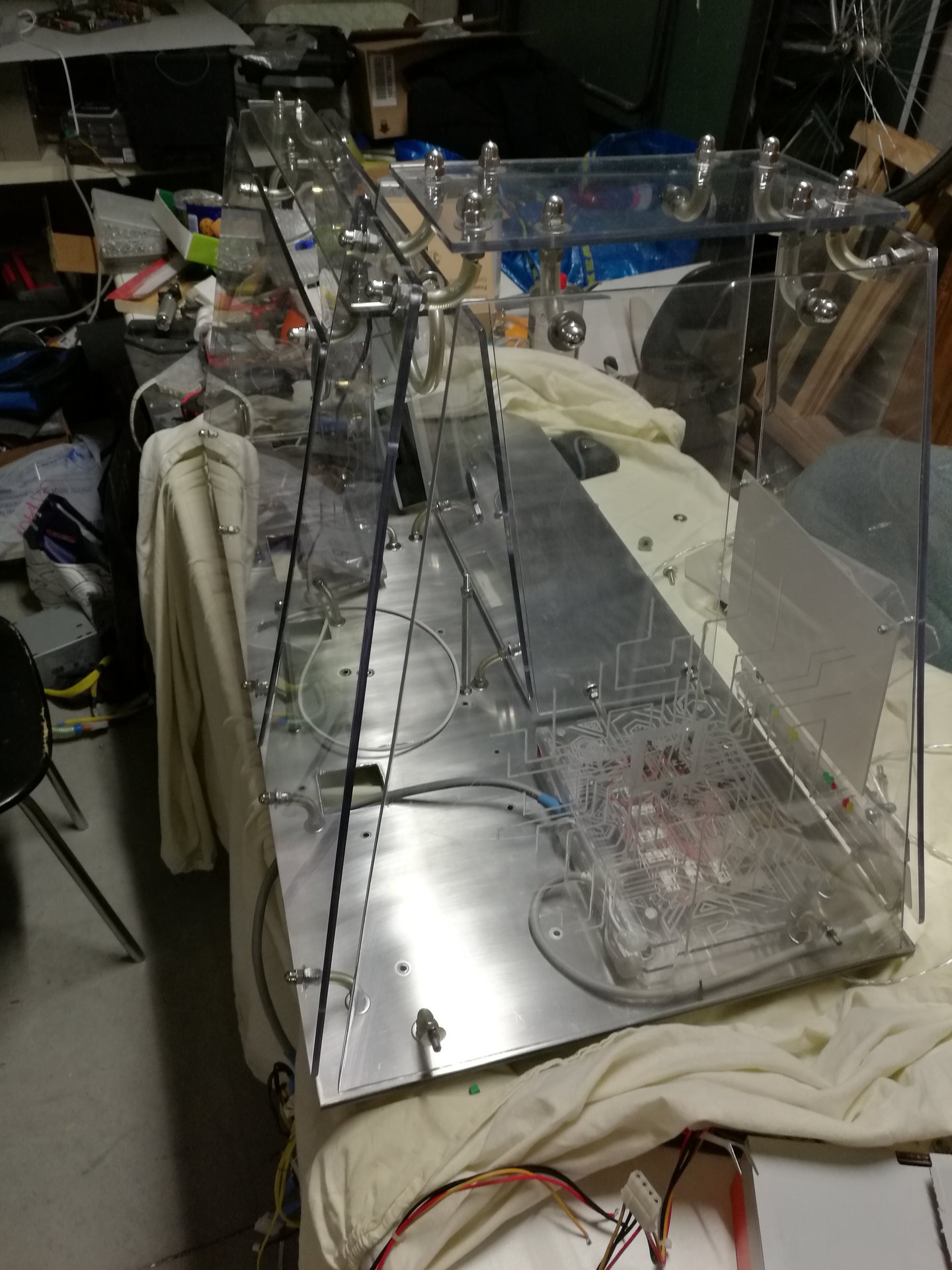
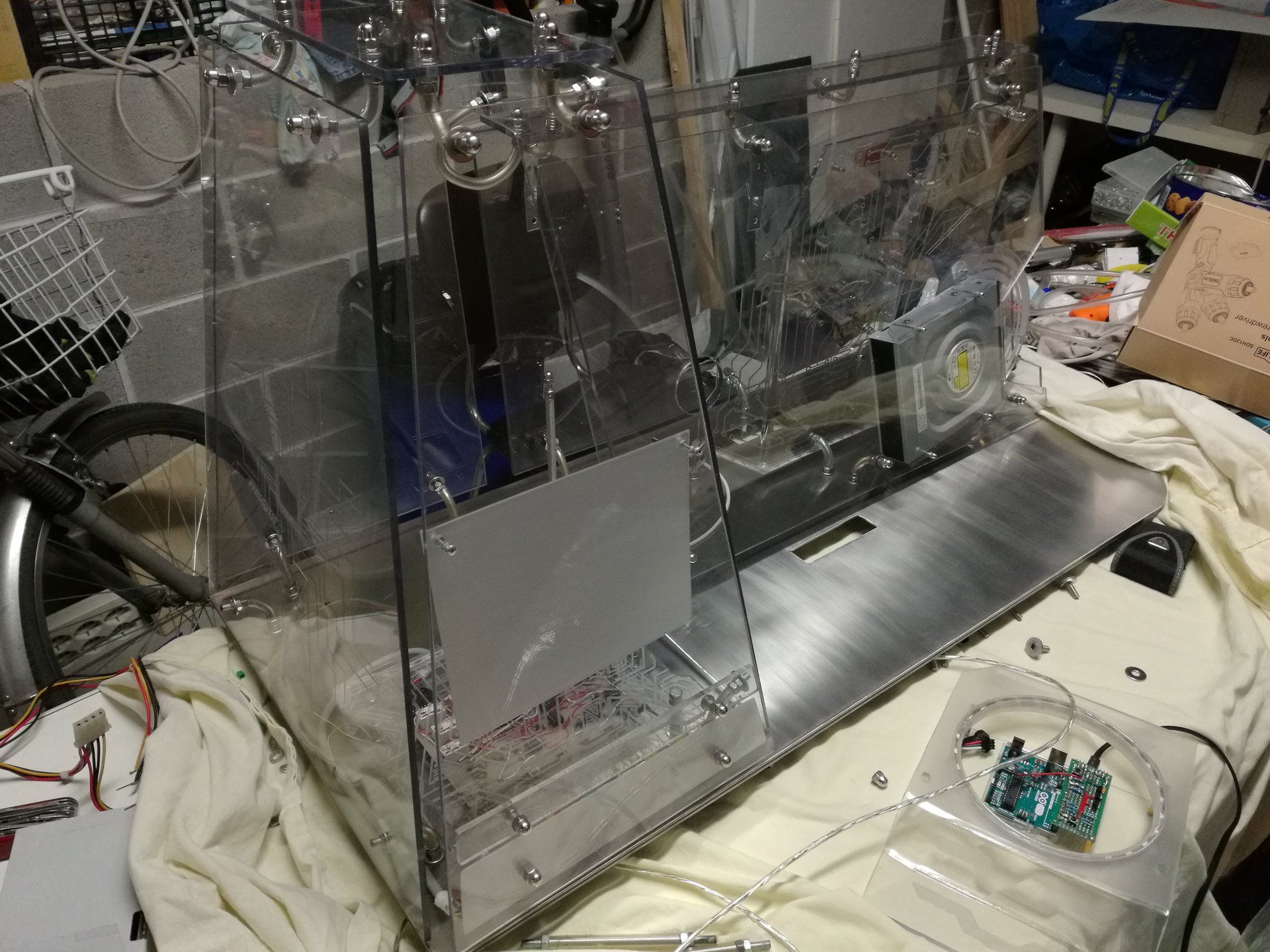
Then I have washed all the remaining case’s parts (the outer walls, the steel base and the structural joints):
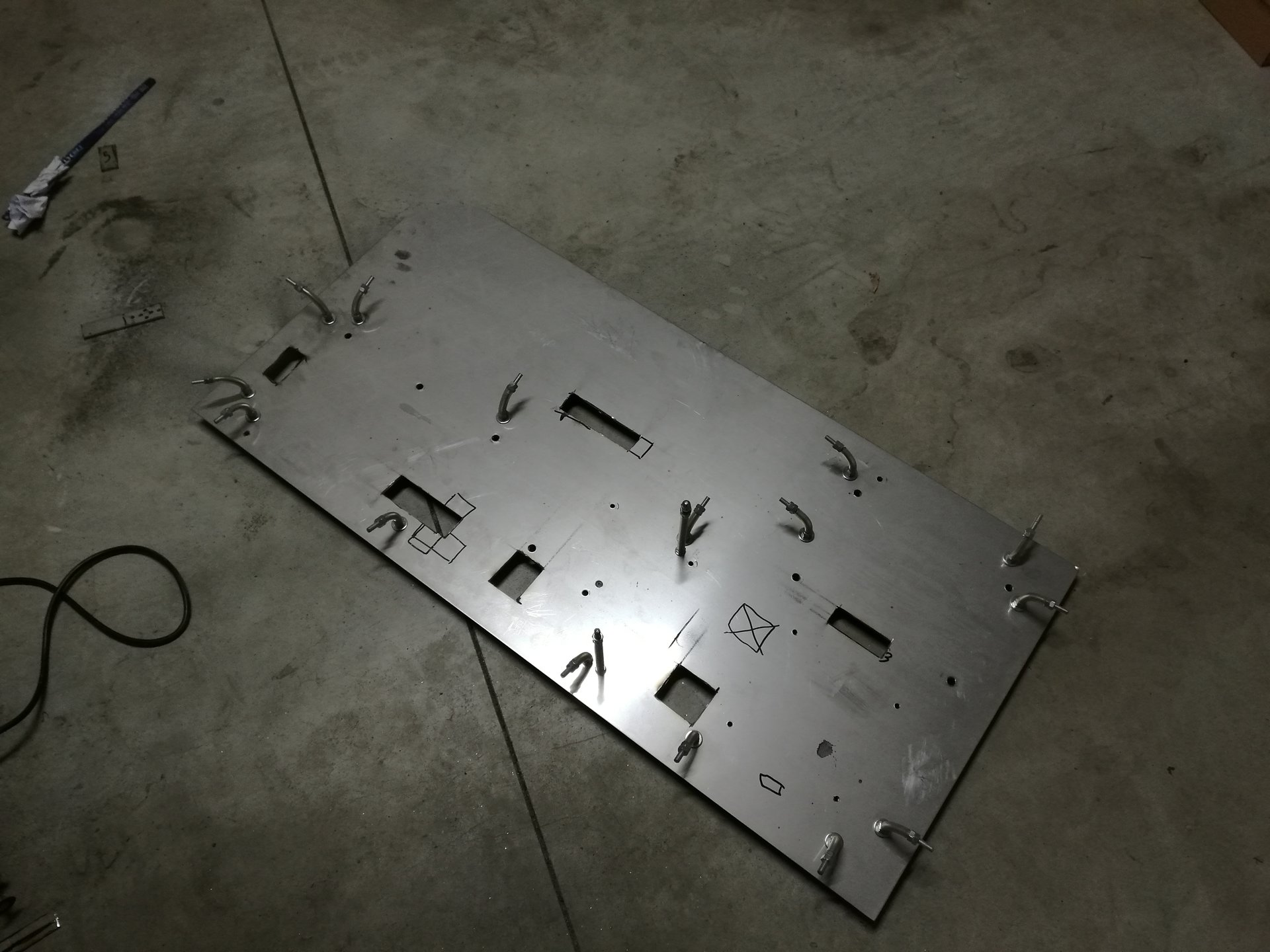
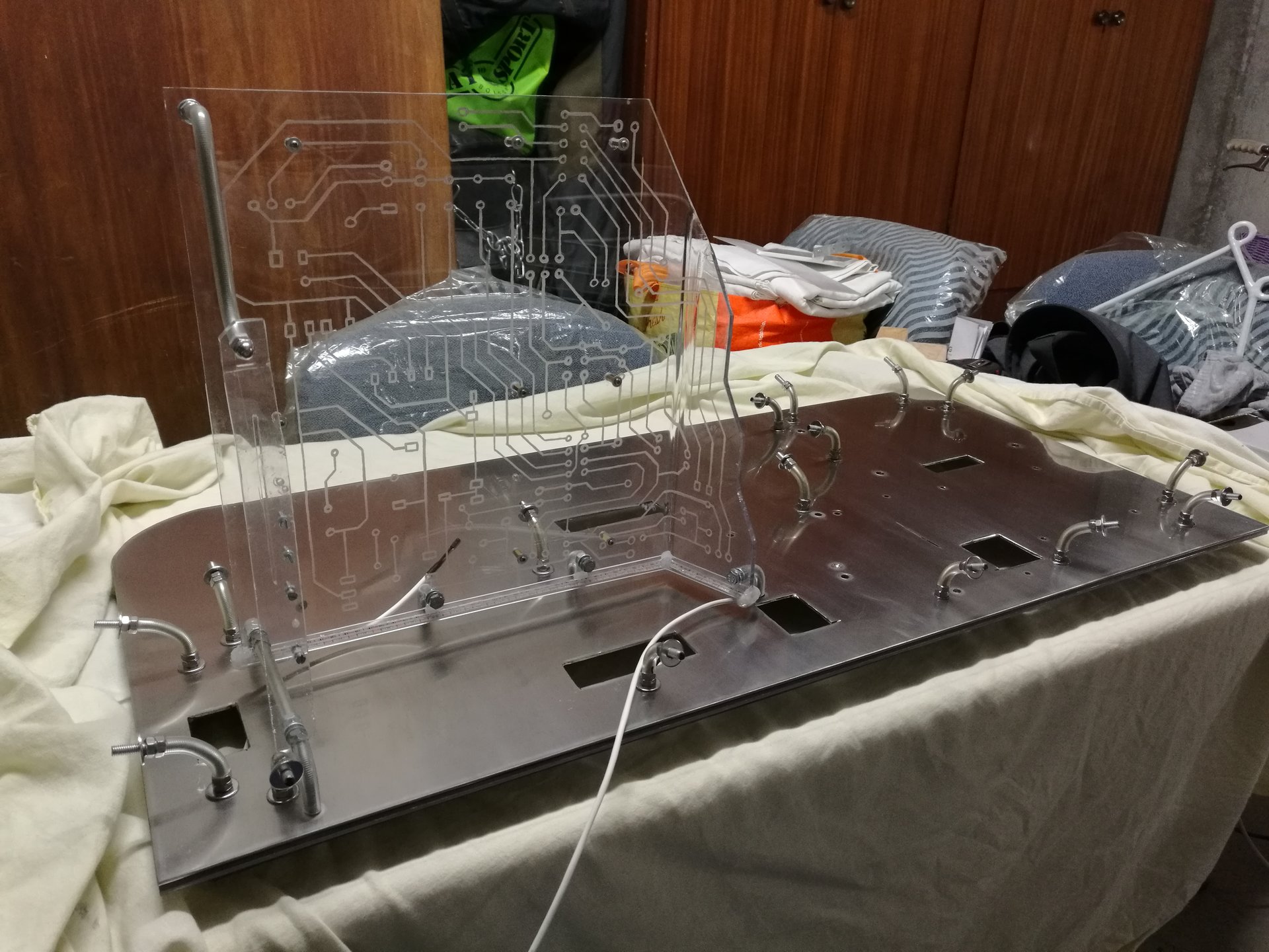
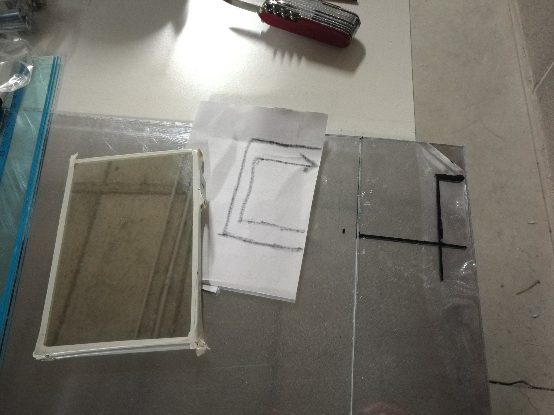
▲ Cutting holes in the base for the cable management
The other thing that I mainly didn’t like of the first Kernel was the terrible cable management, and in the 2.0 version I needed even more cables for the led strips! So I thought that the best solution was to hide all the cables in an interspace under the base.
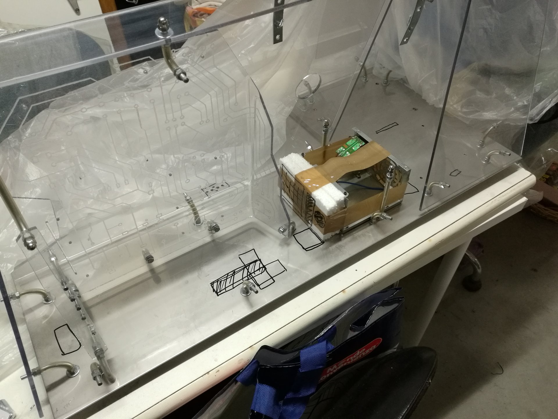
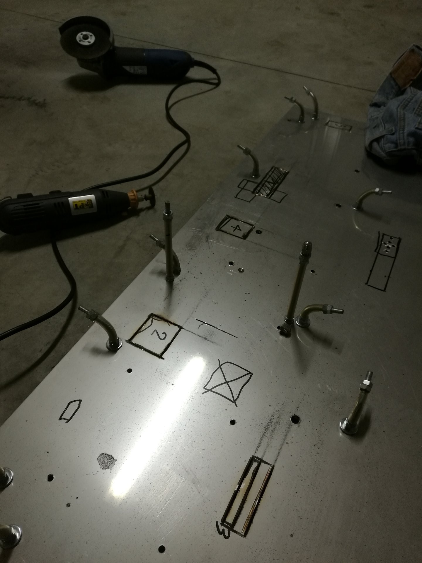
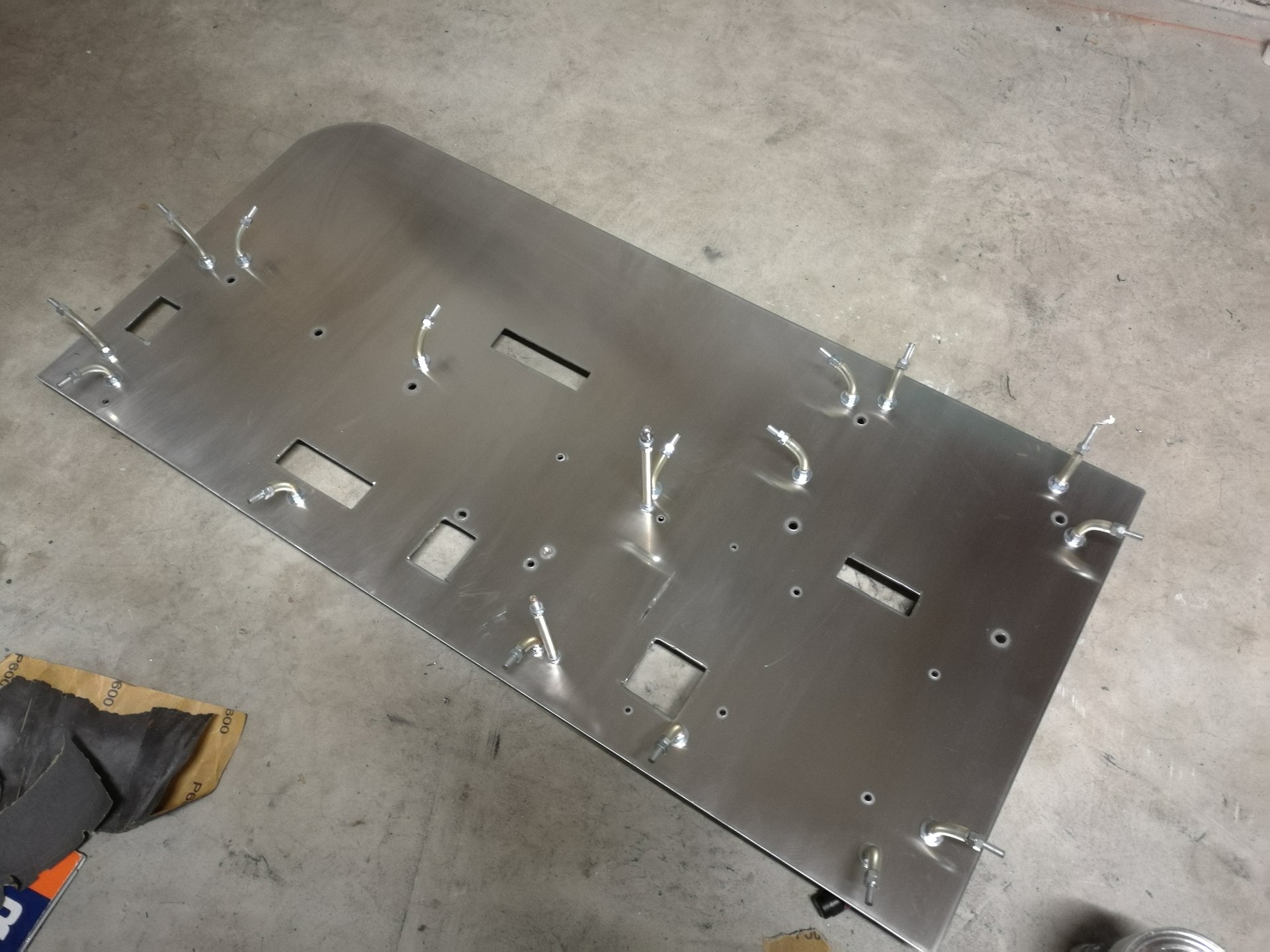
Here I’m marking the position of the holes for the cables, with the help of a dummy PSU (that simulates the size of my current PSU):
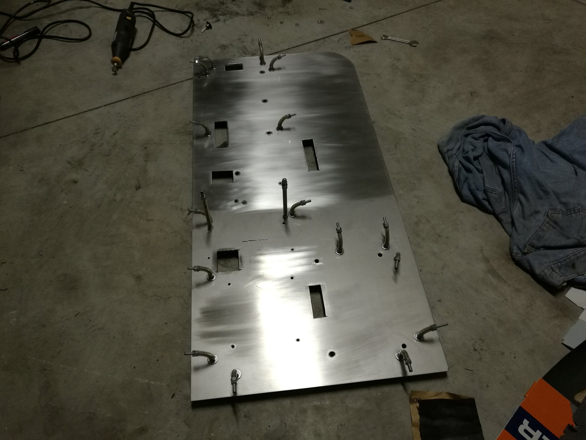
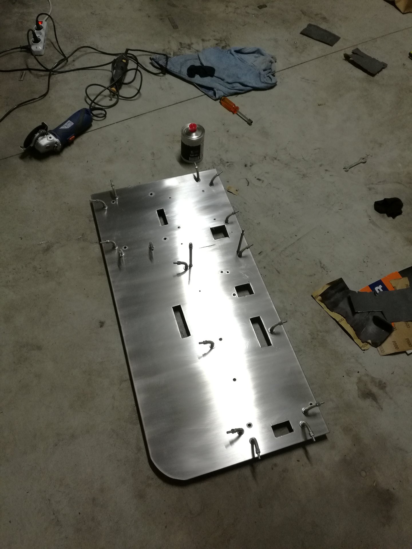
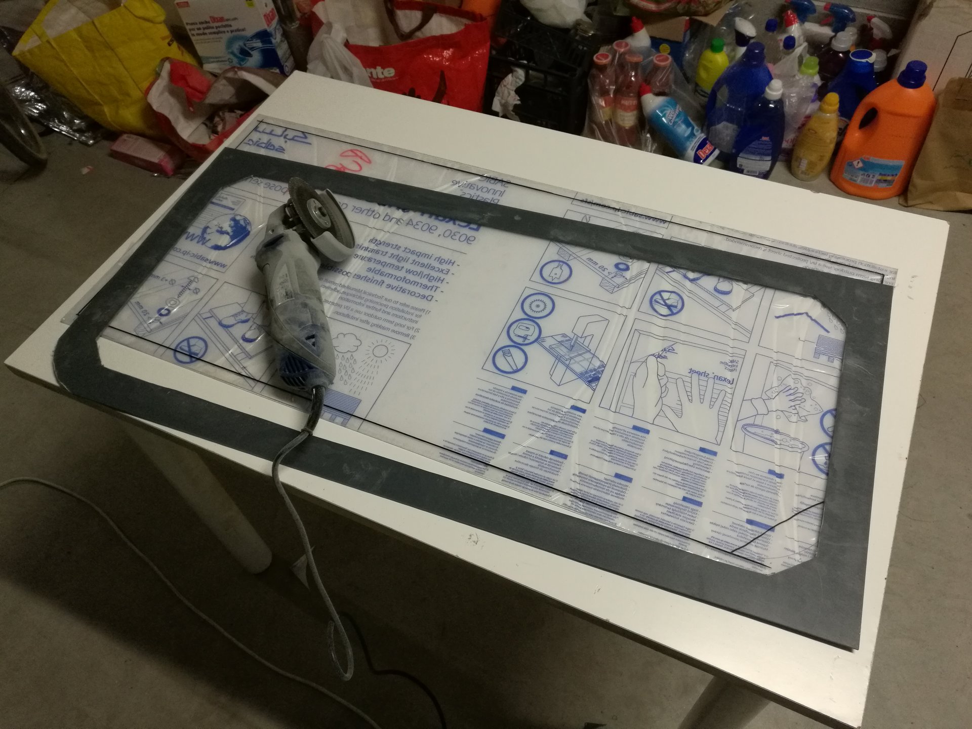
Then I have cutted the holes with an angle grinder:
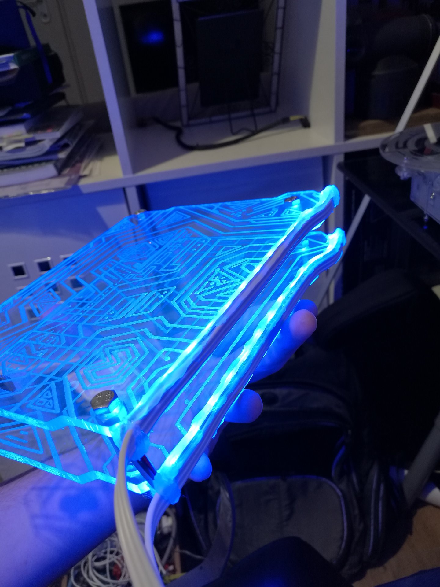
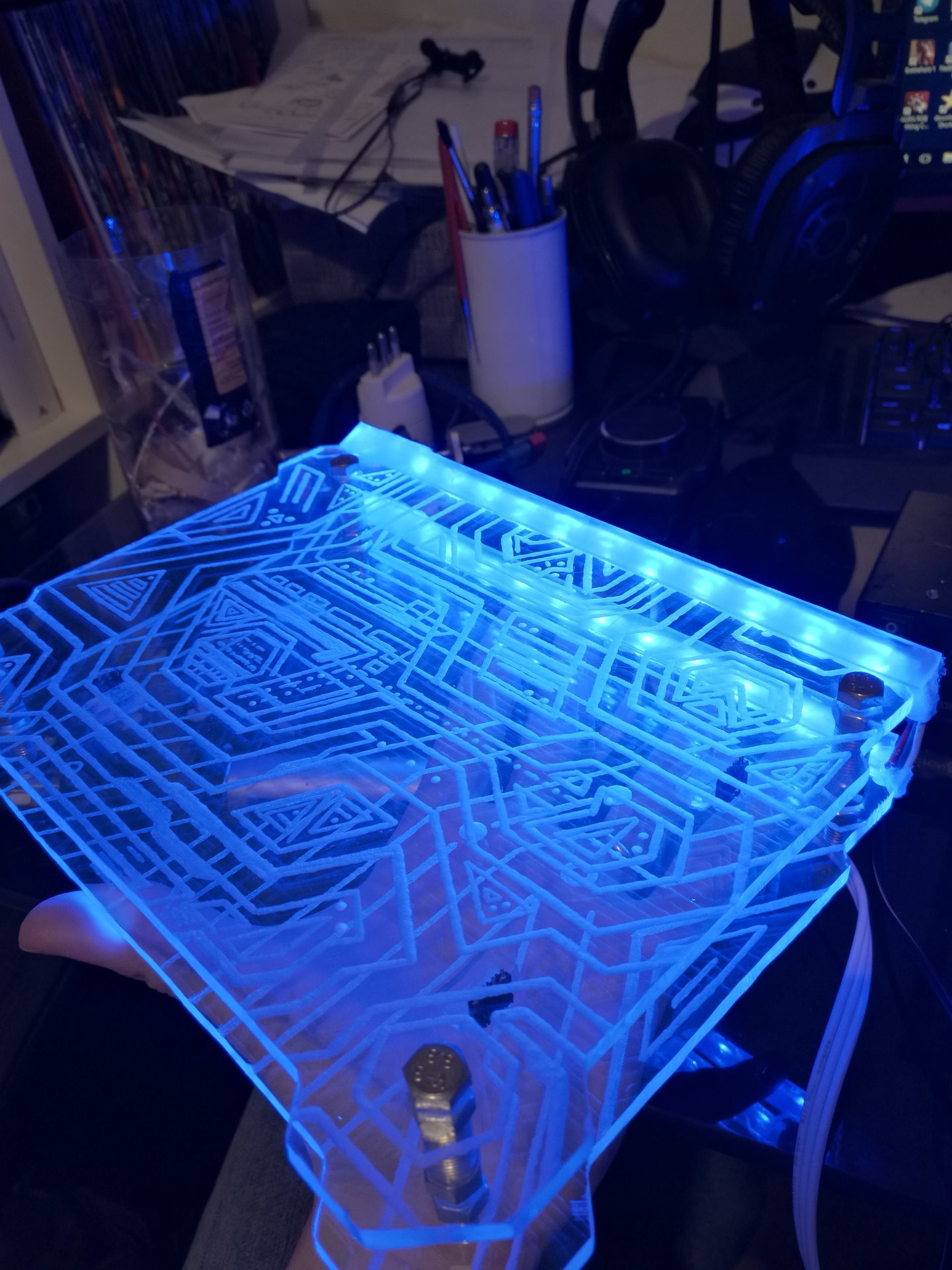
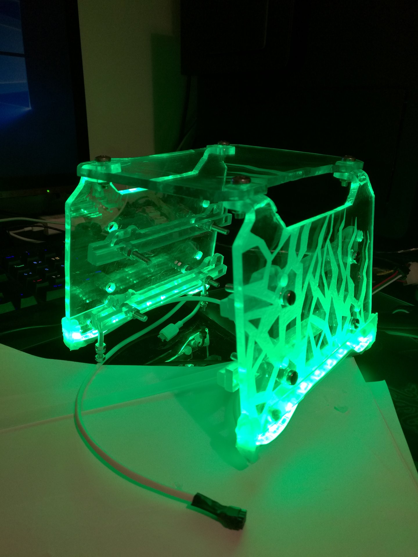
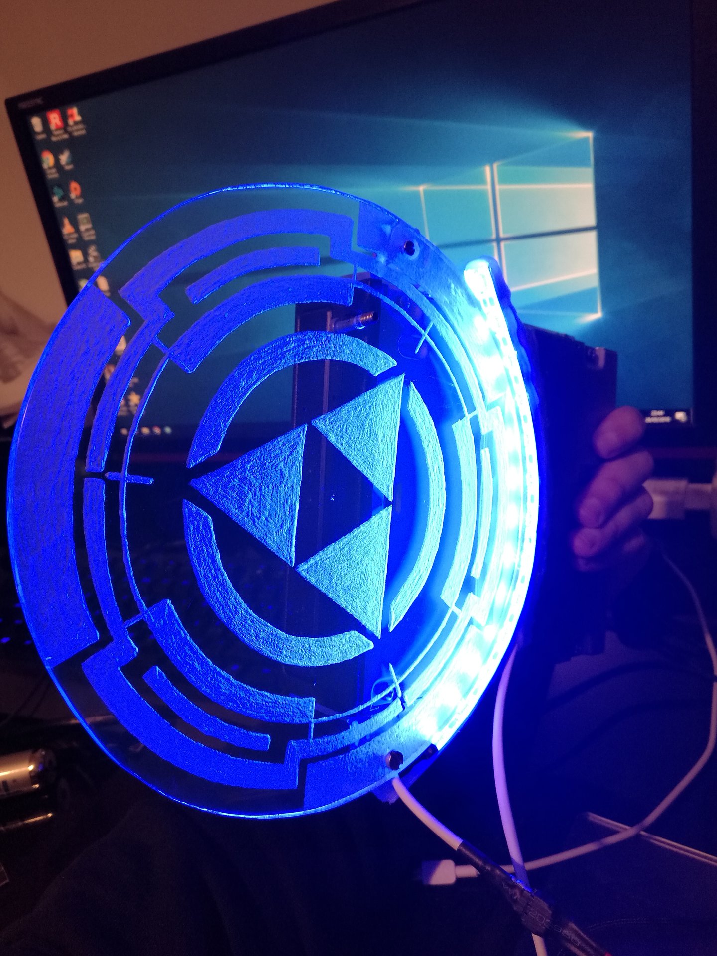
And now, finally this is the main upgrade I have done to the case: a completely redesigned lighting system! 😀
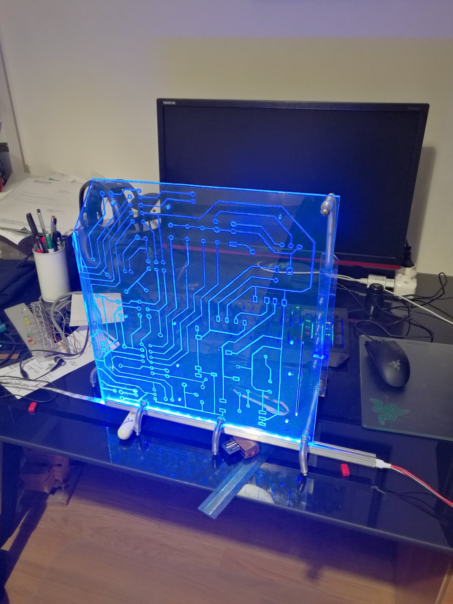
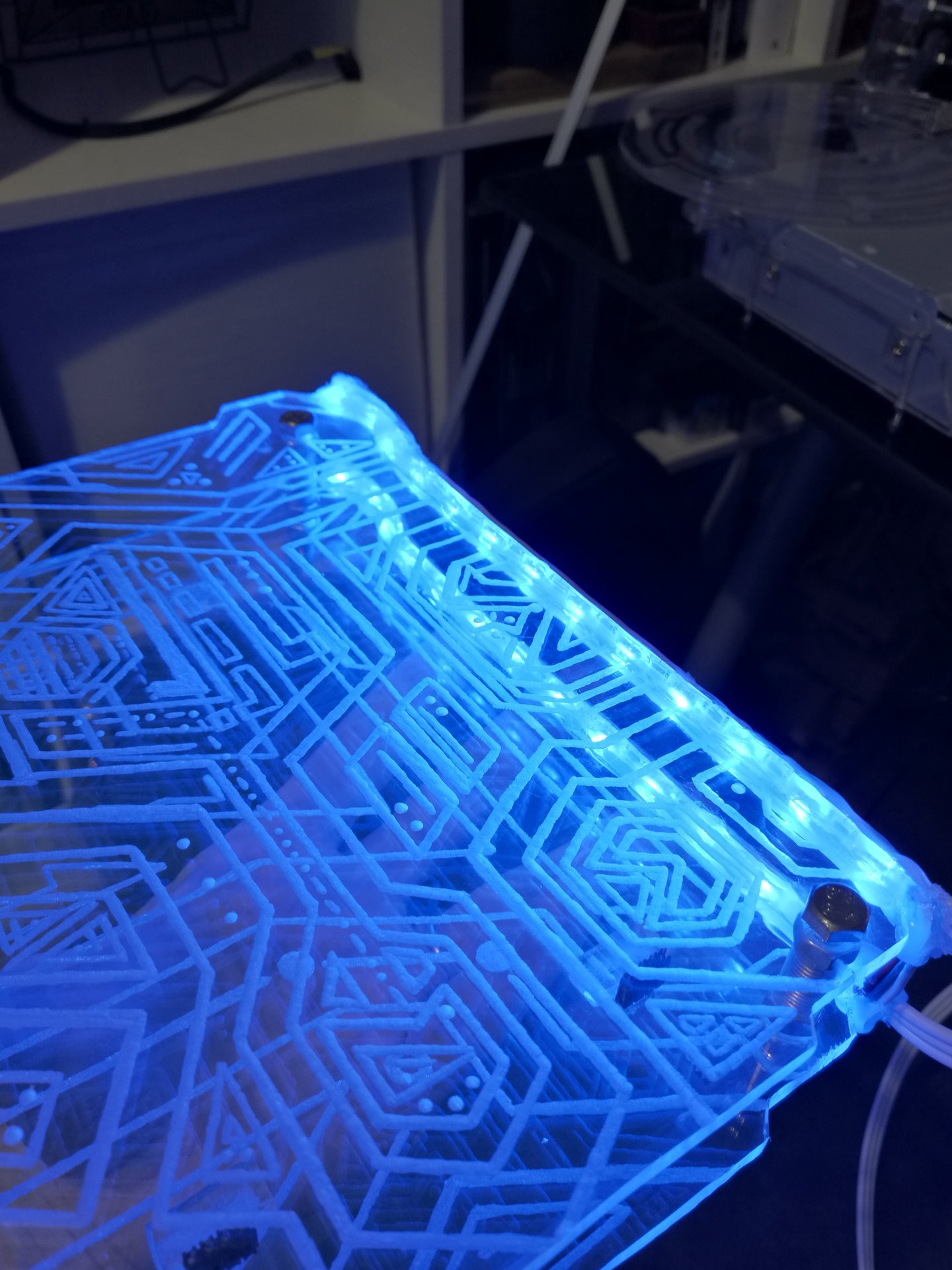
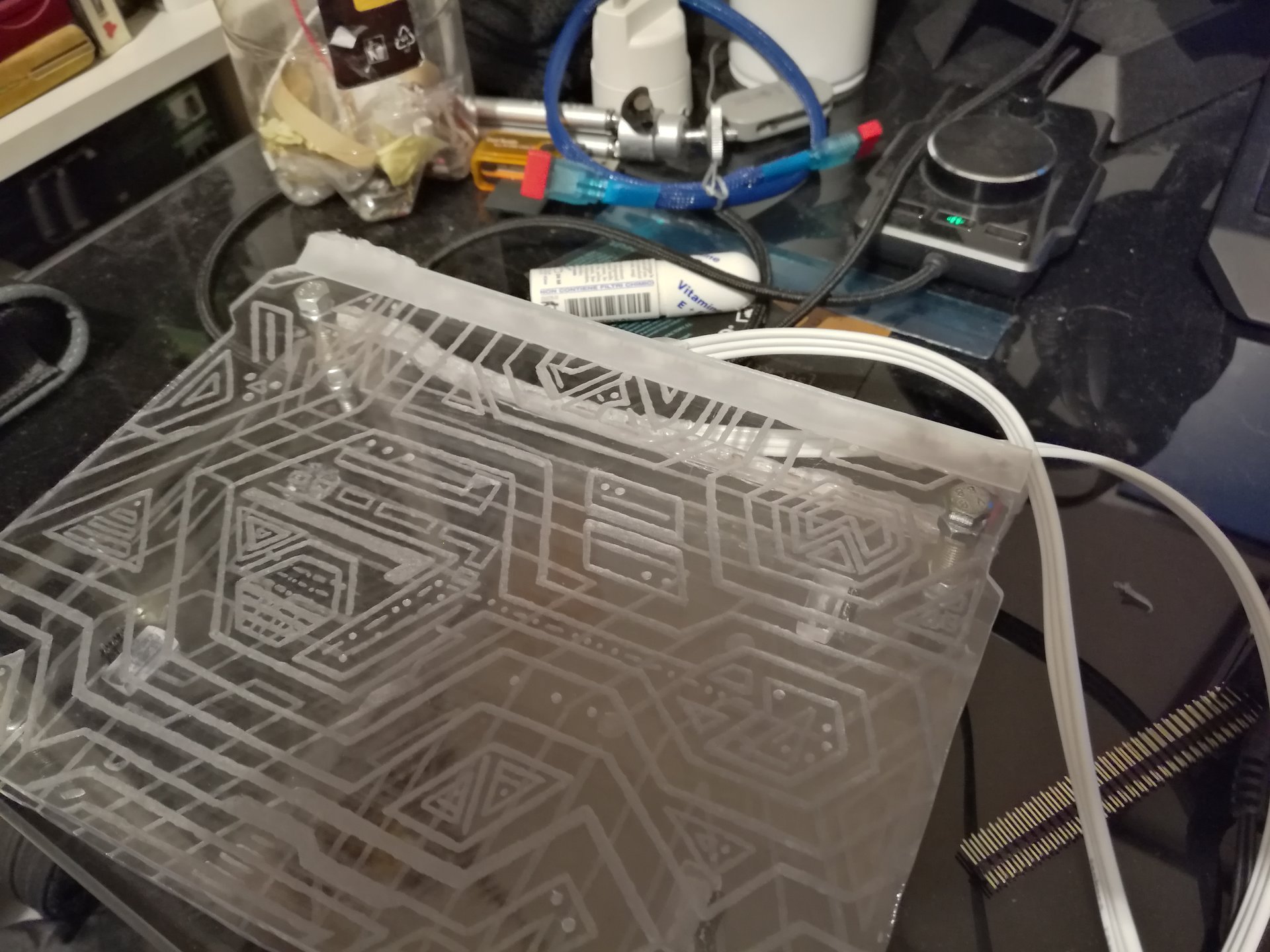
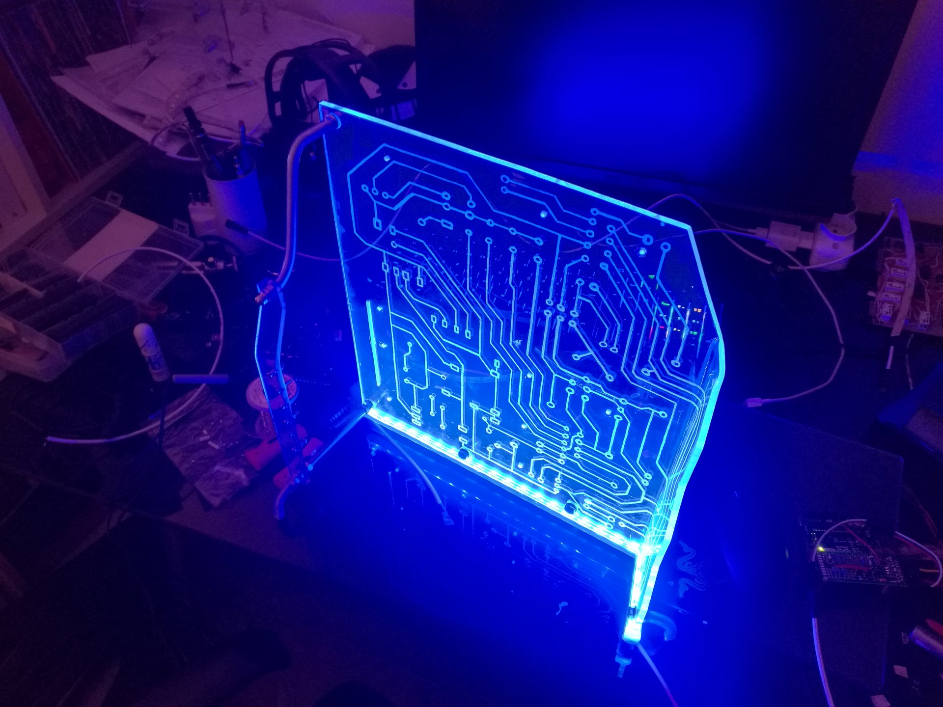
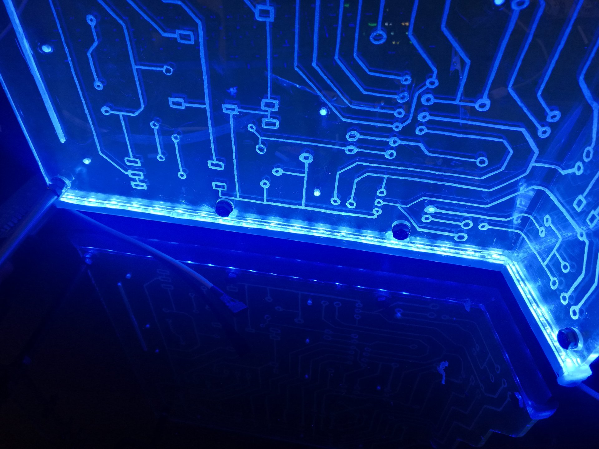
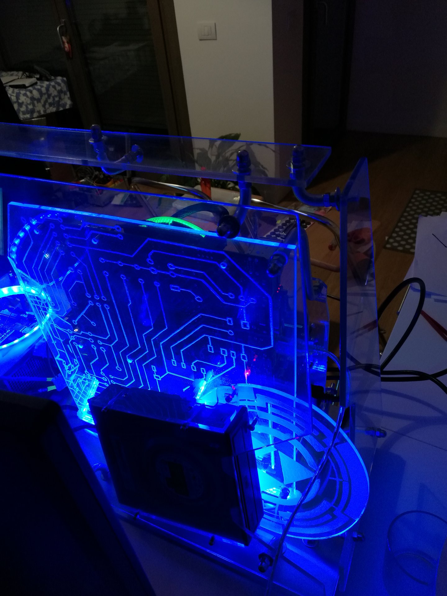
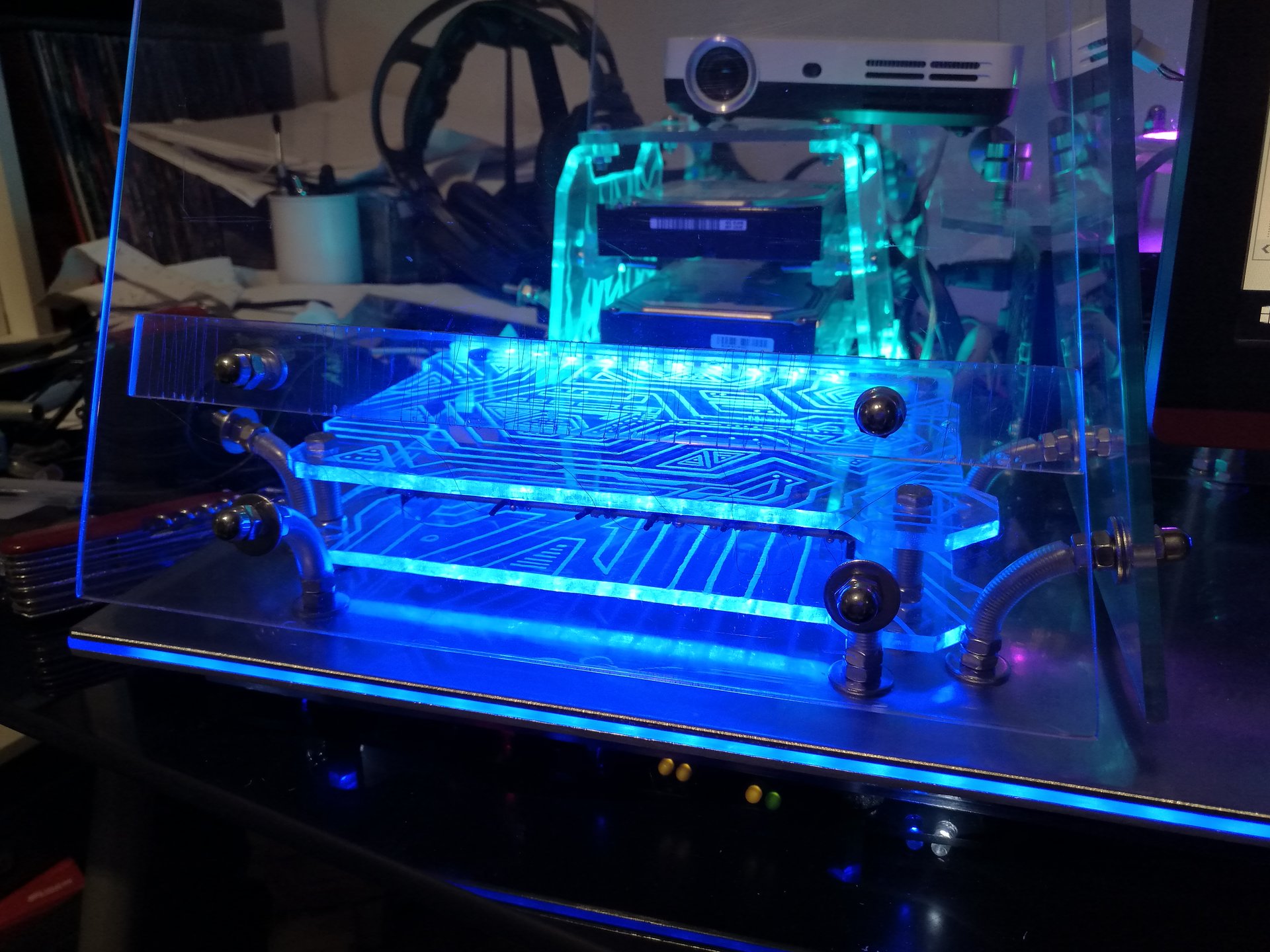
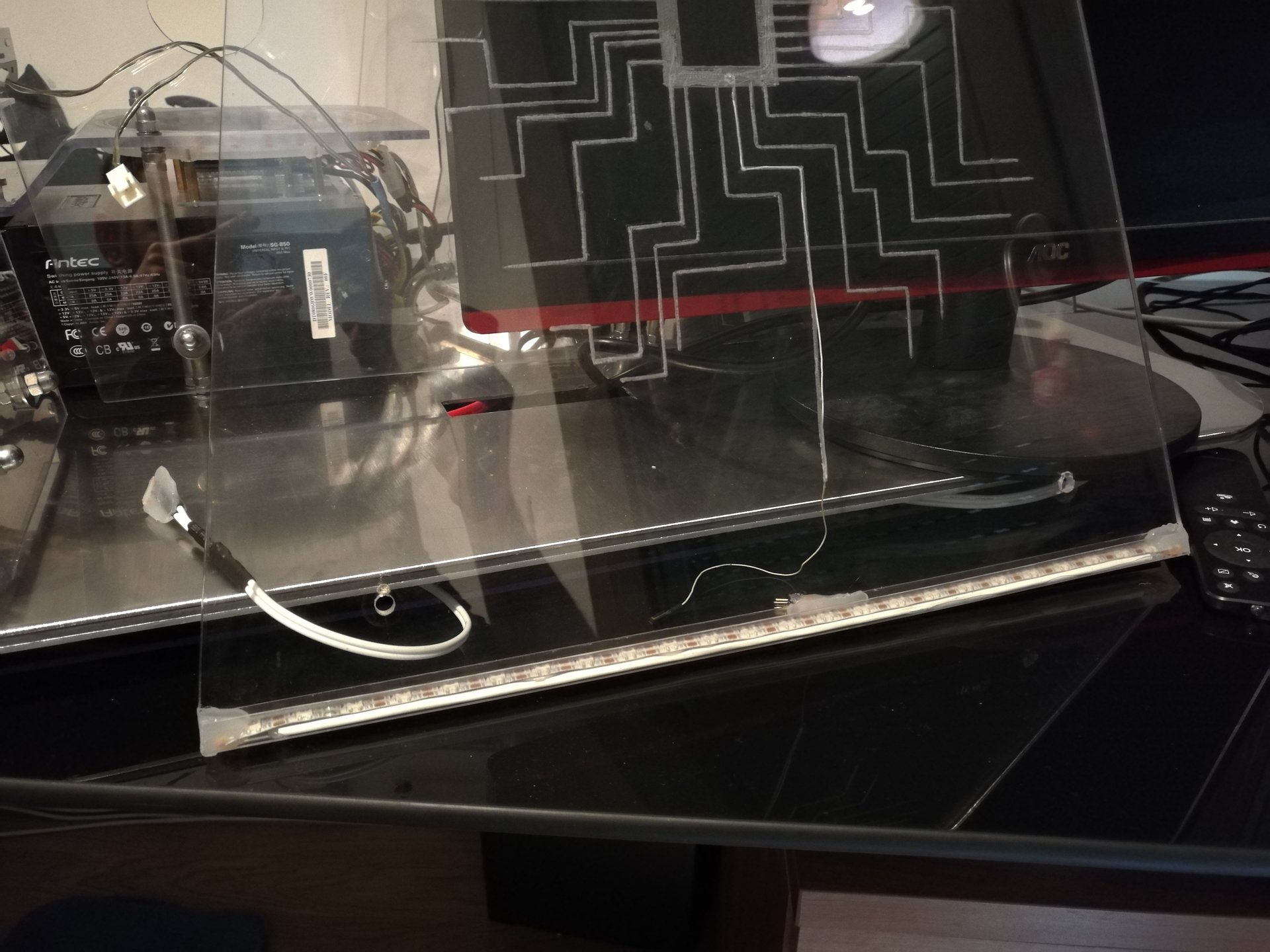
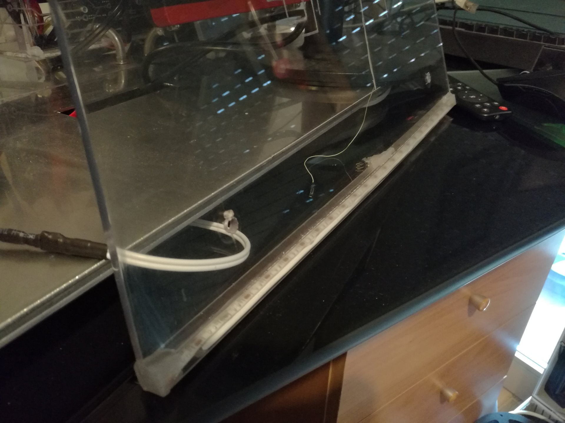
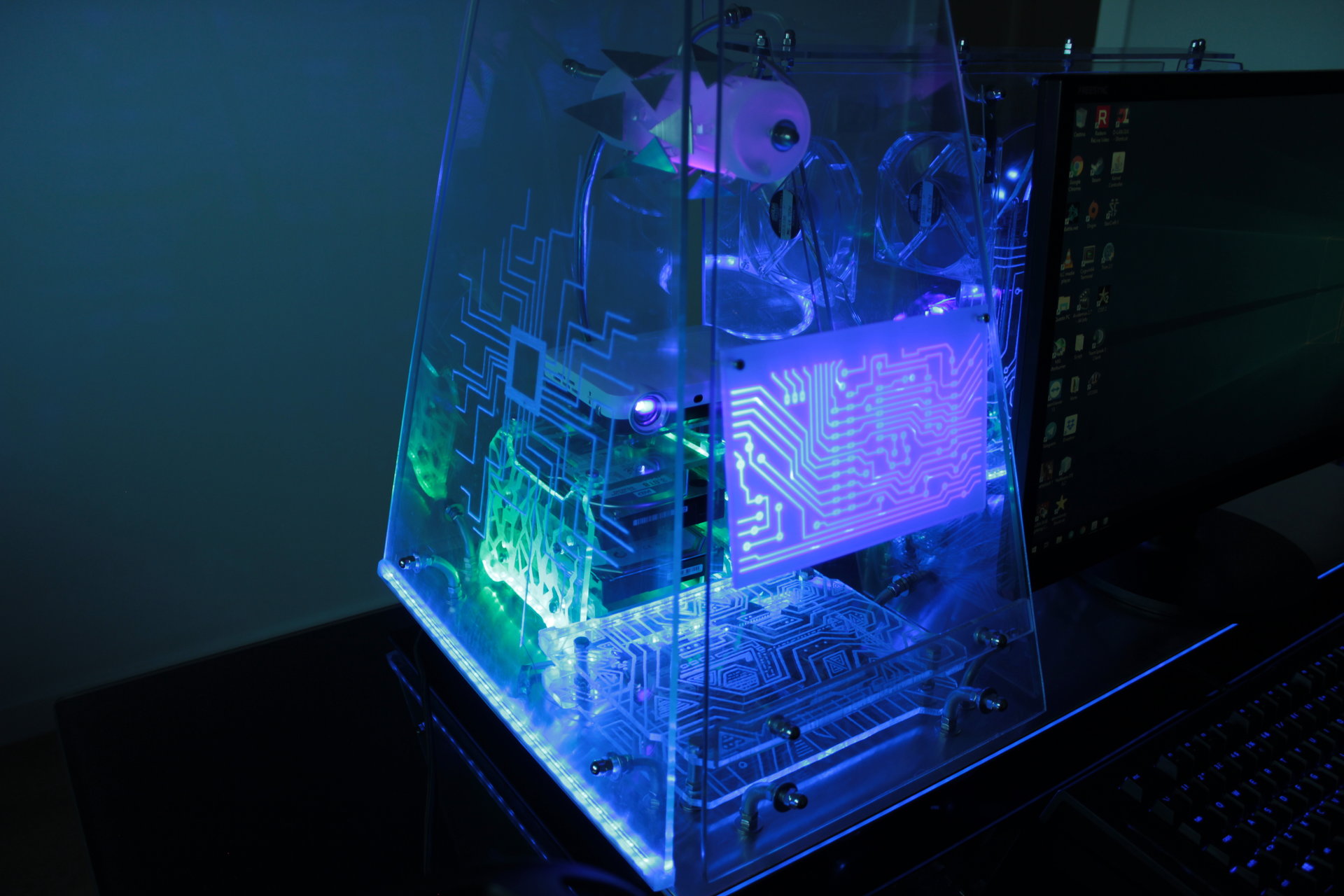
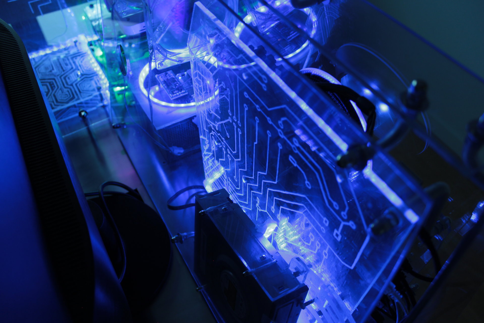
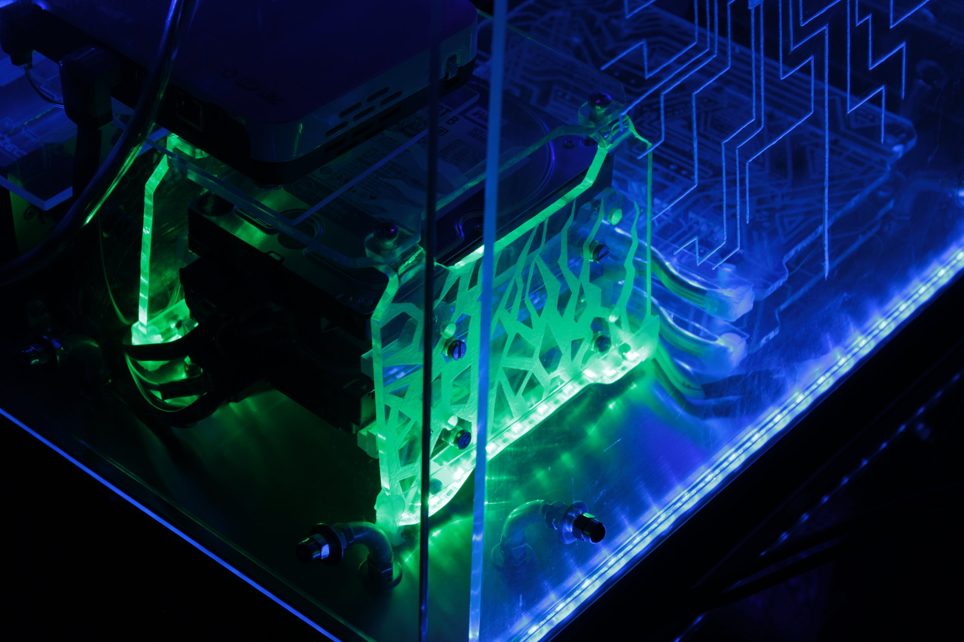
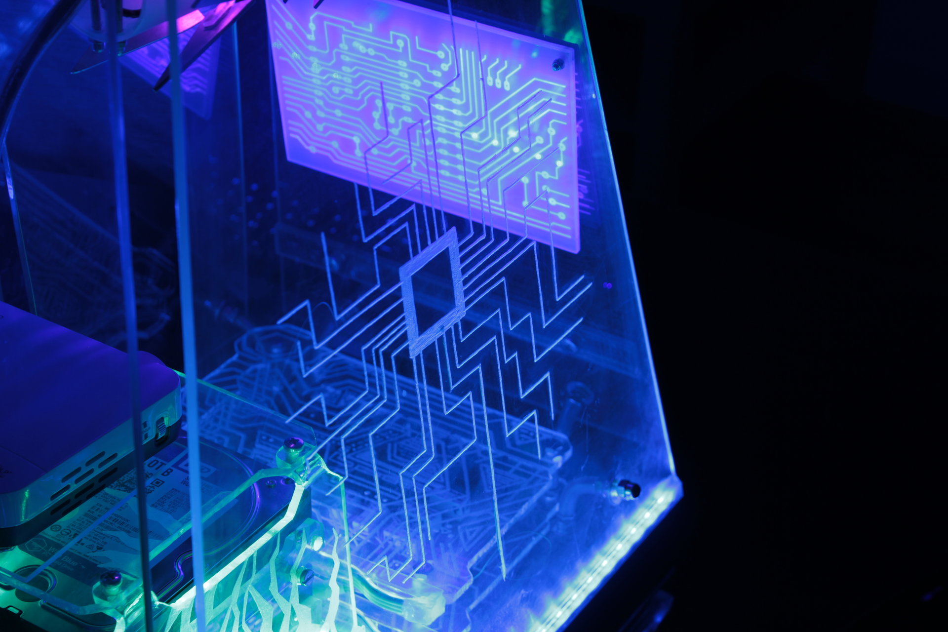
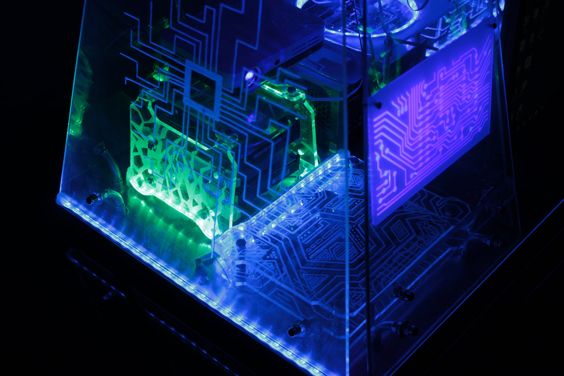
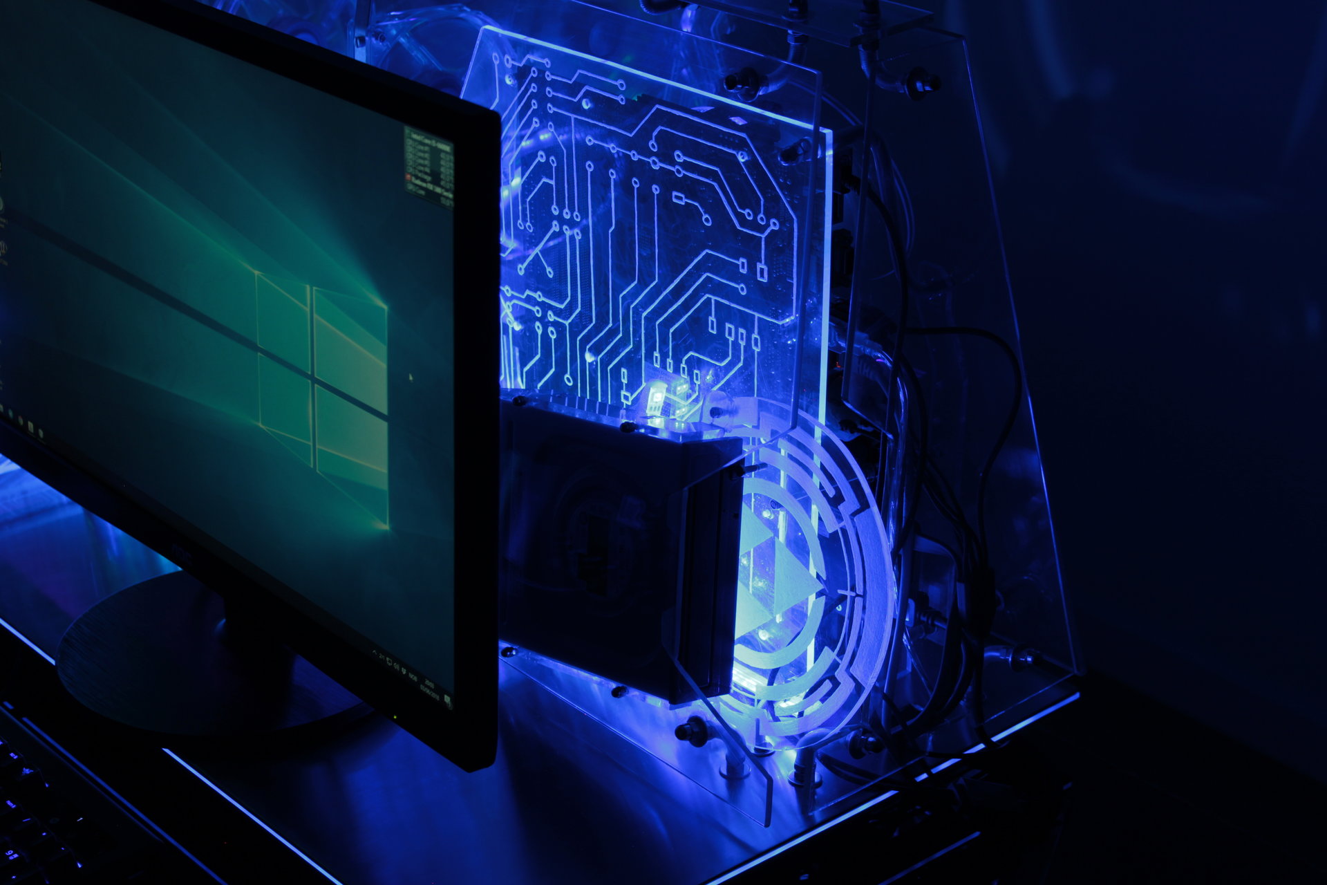
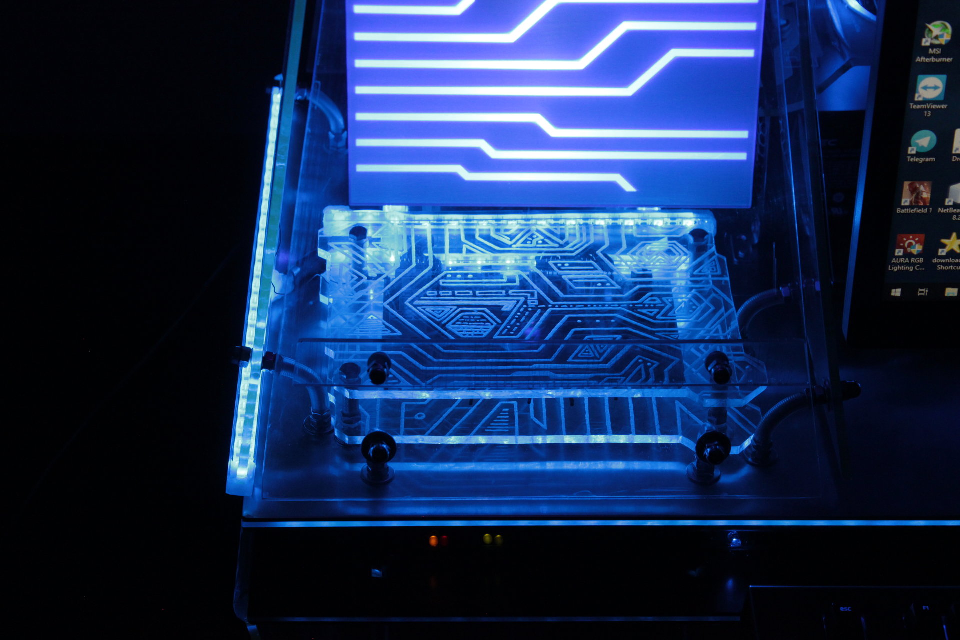
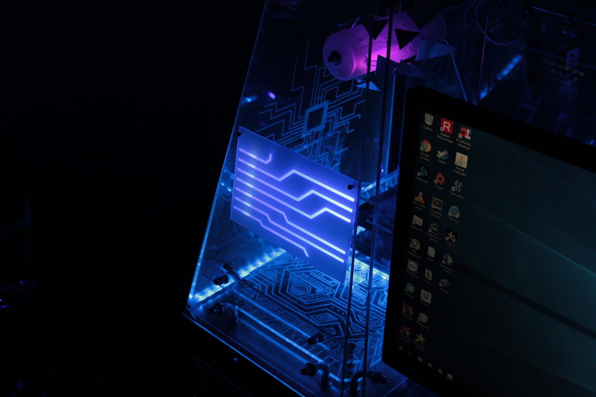
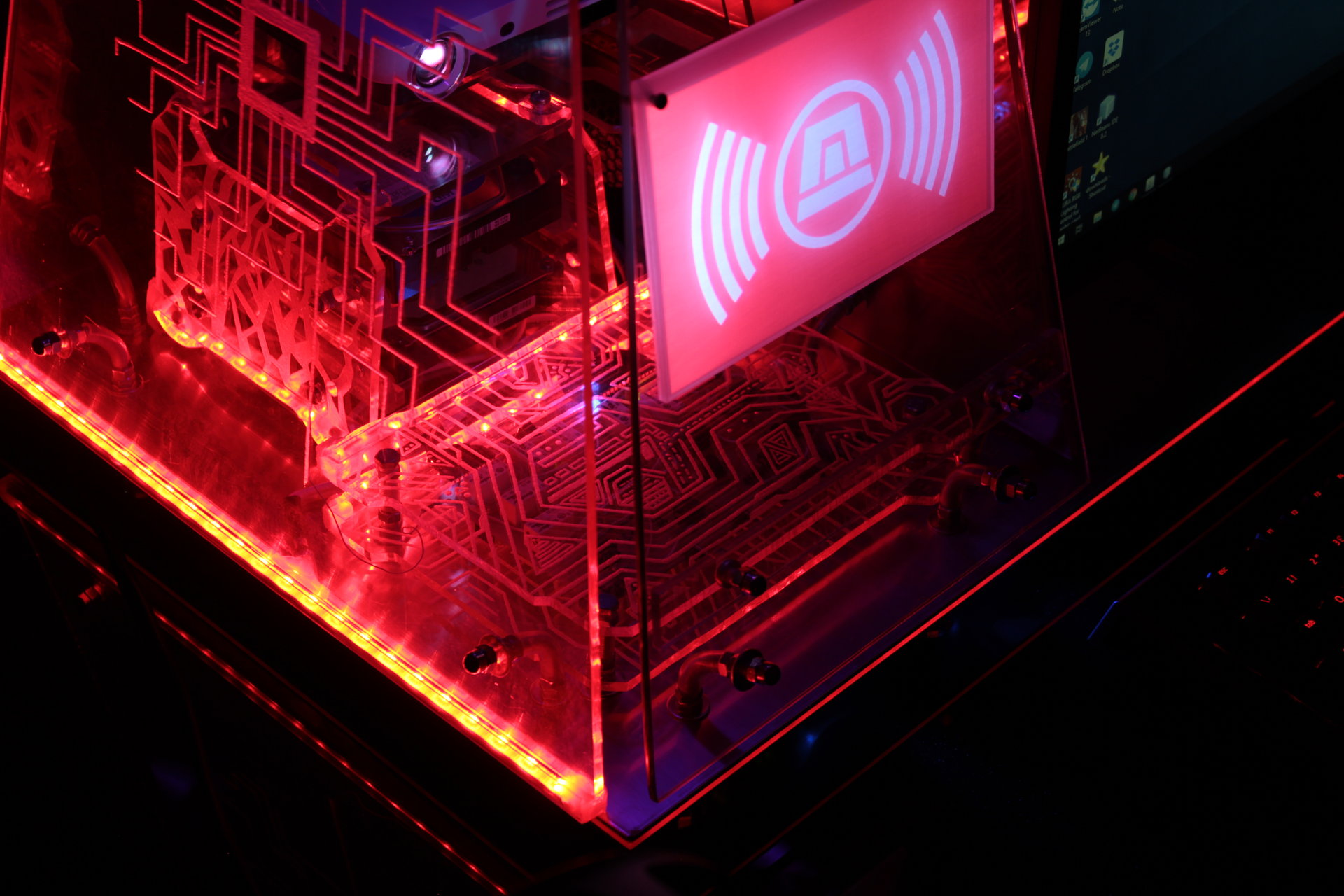
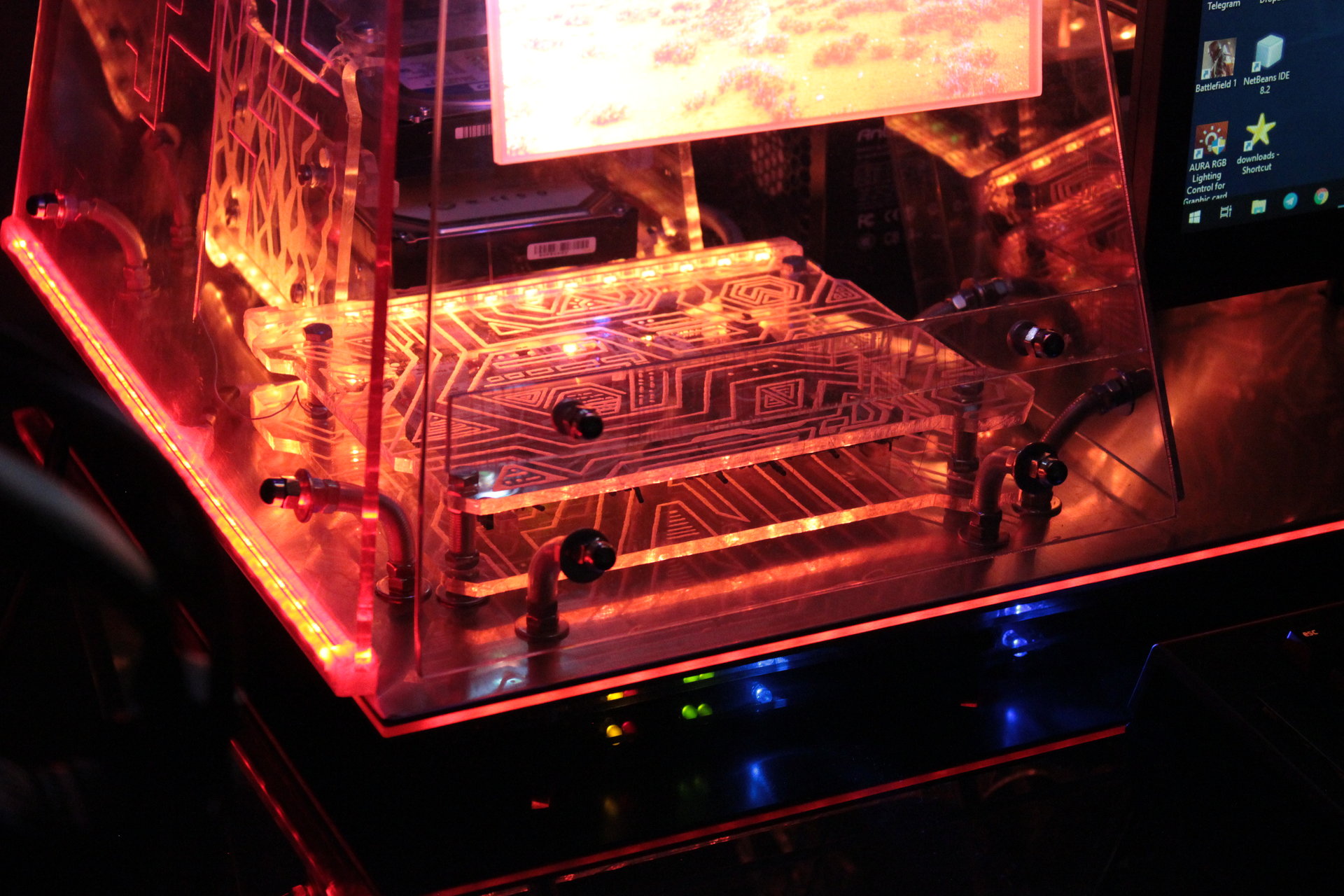
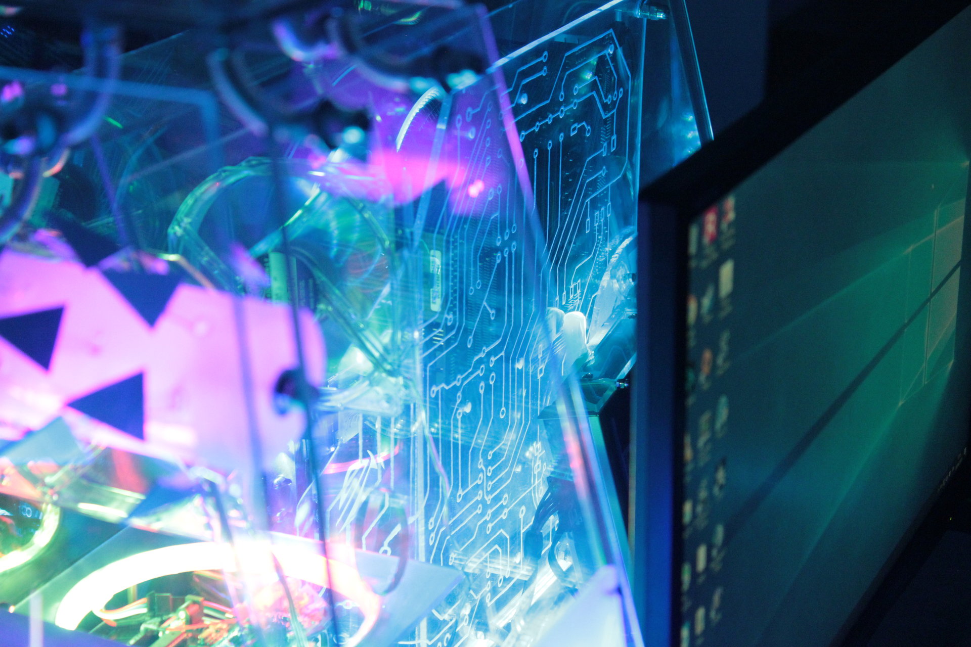
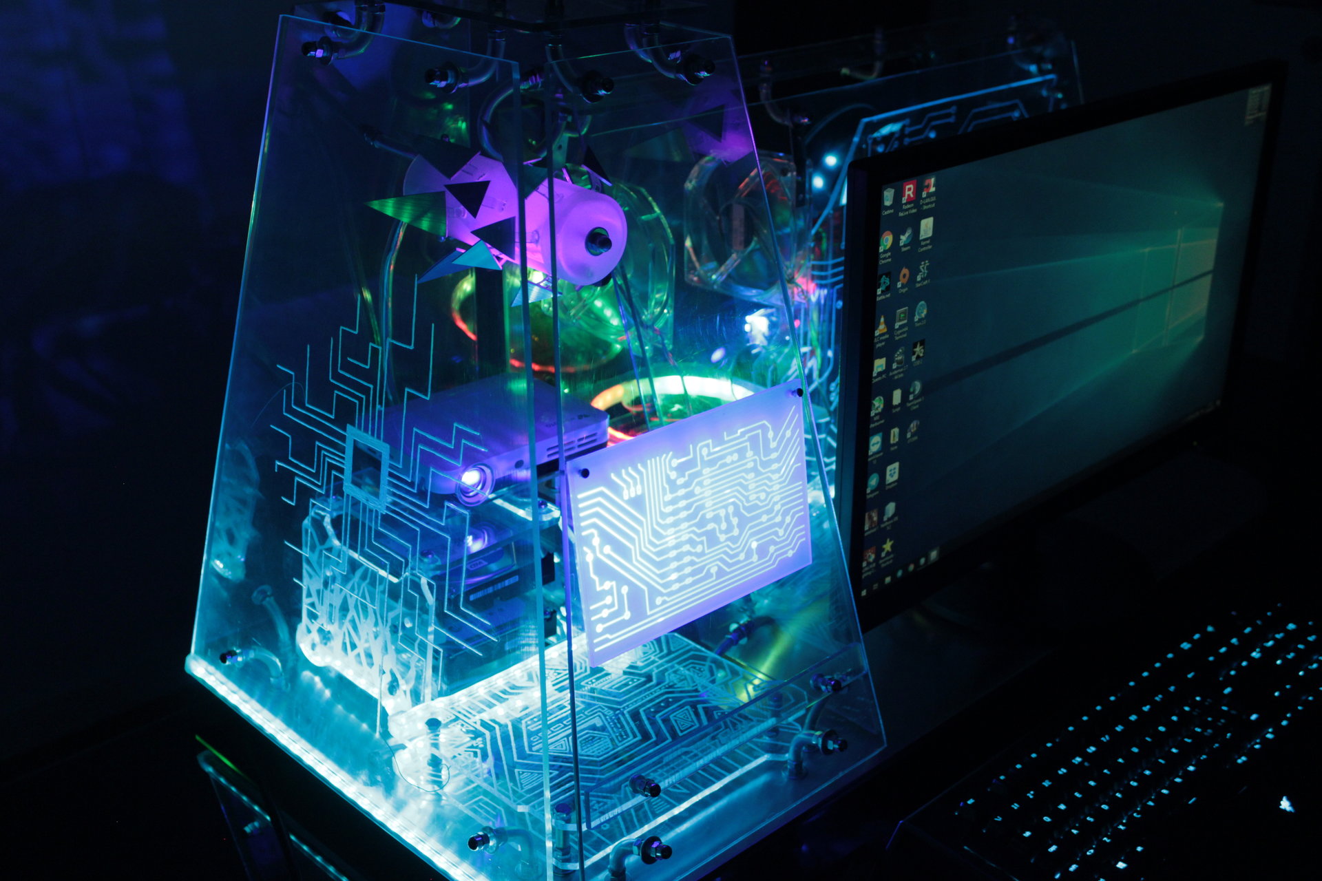
As I said before, to obtain the best lighting of the engraved panels, I had to shot a concentrated beam of light directly in the edge of the panels, so I had to attach the led strips directly on the bottom edge of each engraved panel.
The problem was: how to fix them in that position? I had to try some different solutions before finding the right one.
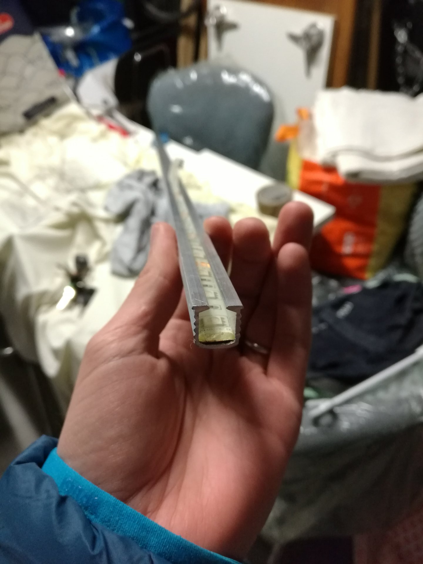
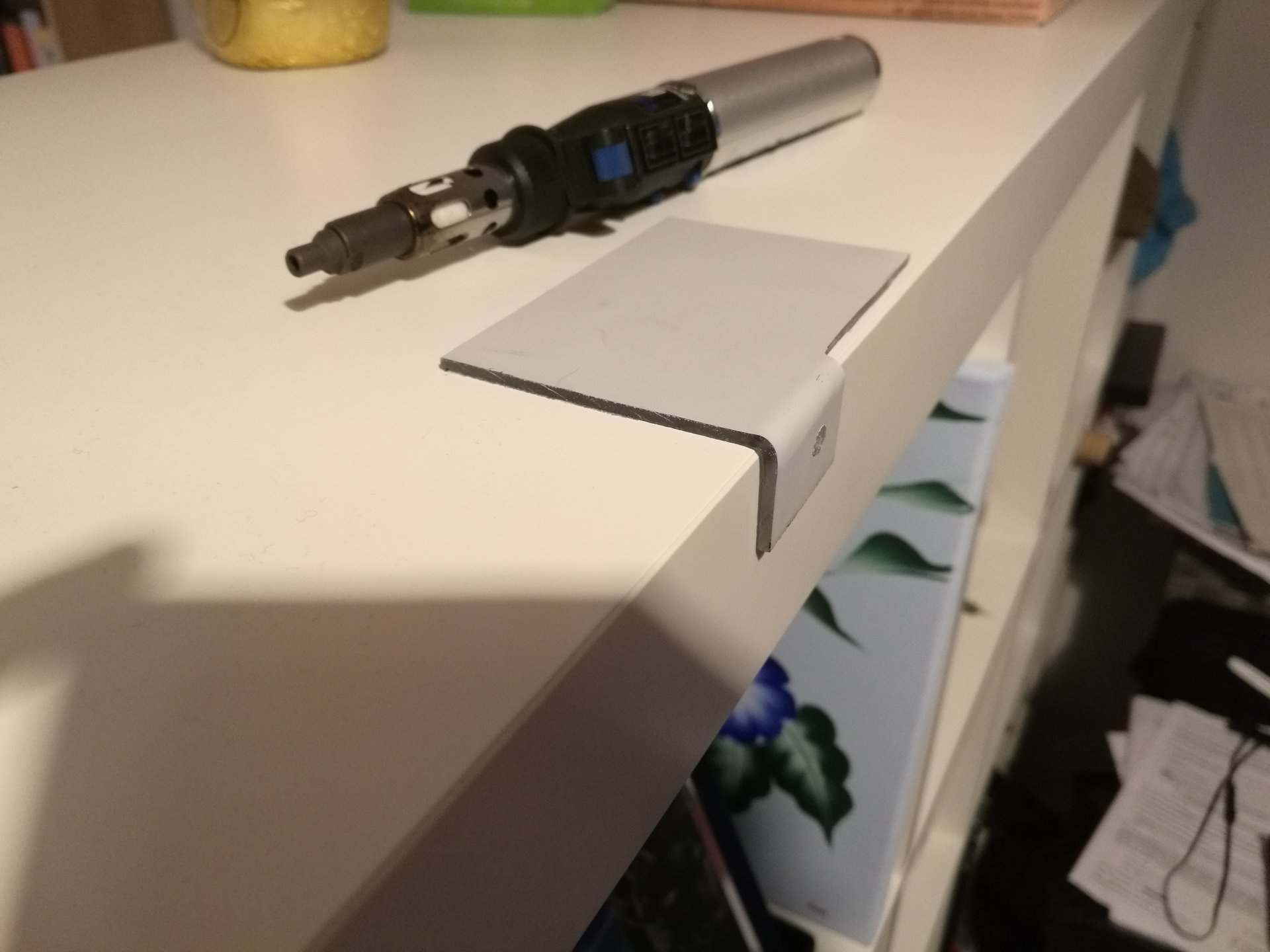
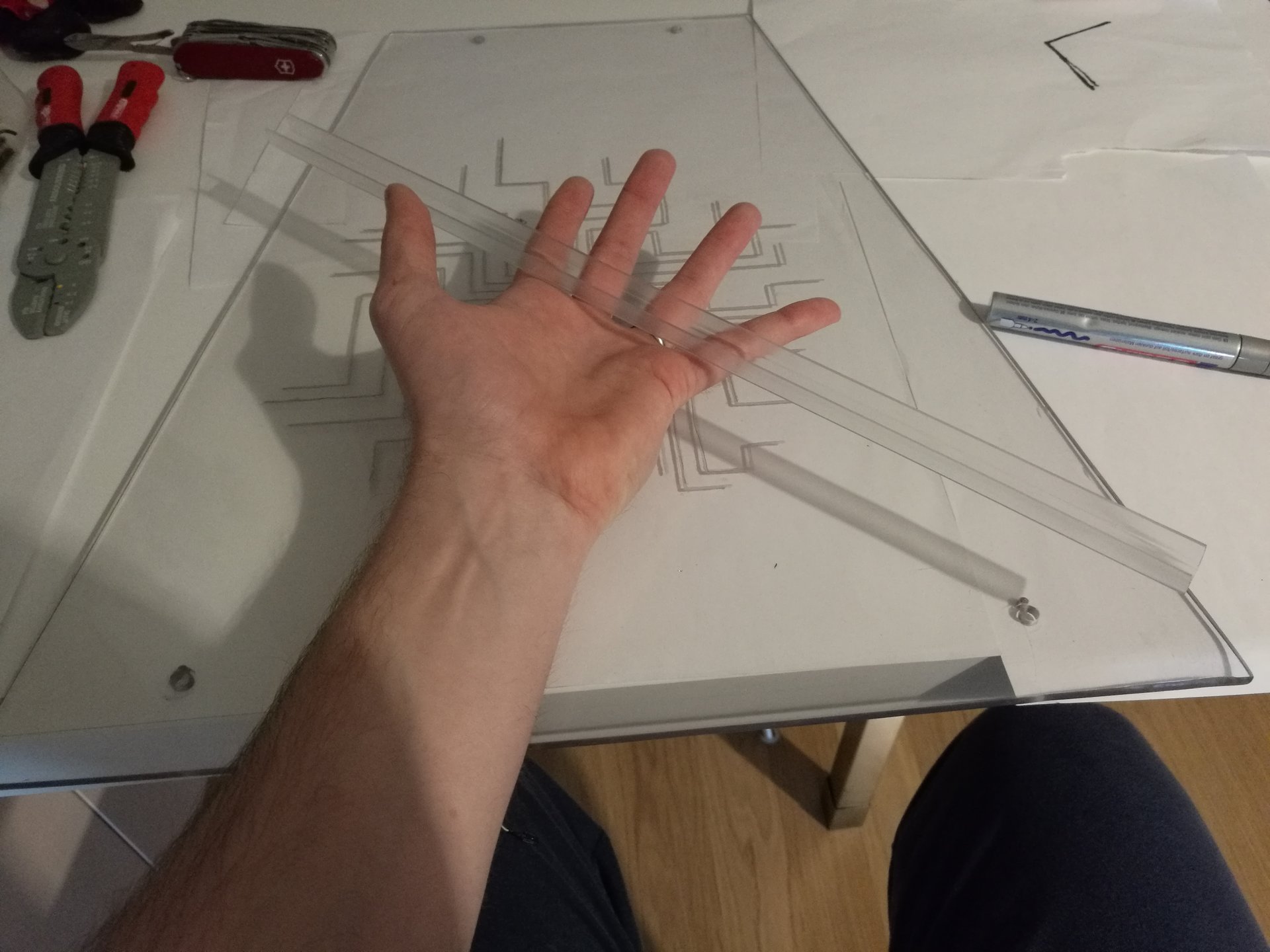
First I have tried this aluminium profile, but I thought it appeared too bulky, and it reduced the lighting of the engravings:
Then I tried to glue the led strips directly on the panels with hot glue, but I didn’t like at all the irregular surface of the hot glue:
another try: covering the hot glue with some sanded polycarbonate bars… it was better than the previous tries, but I didn’t like the result anyway:
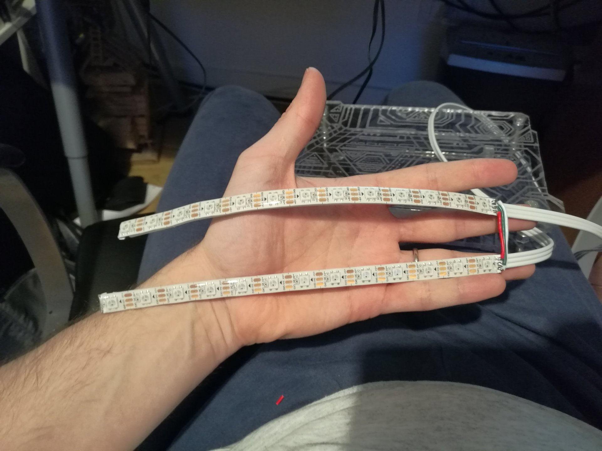
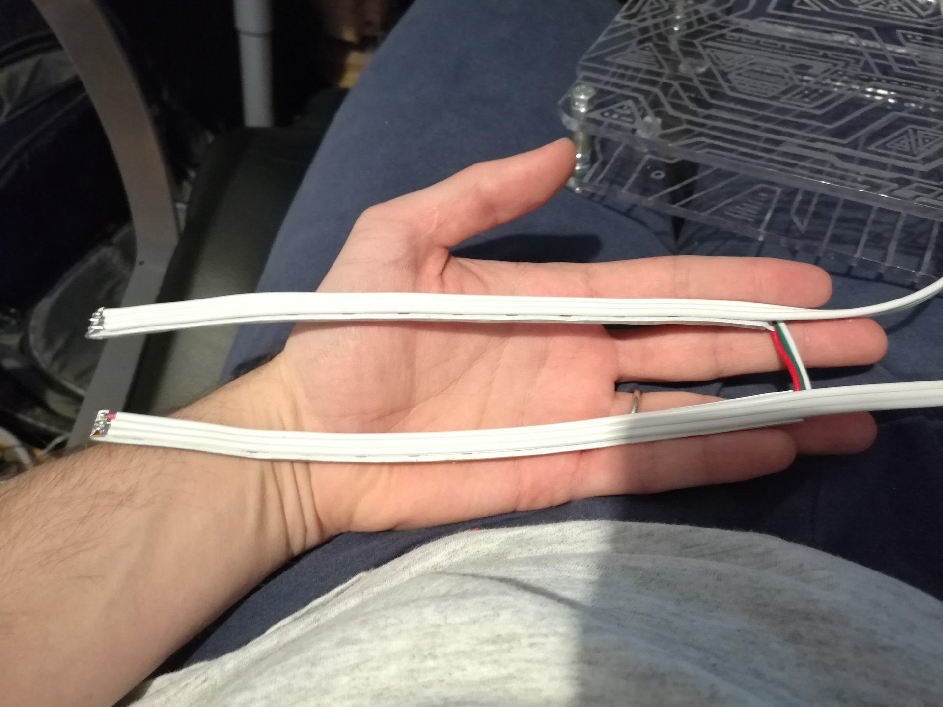
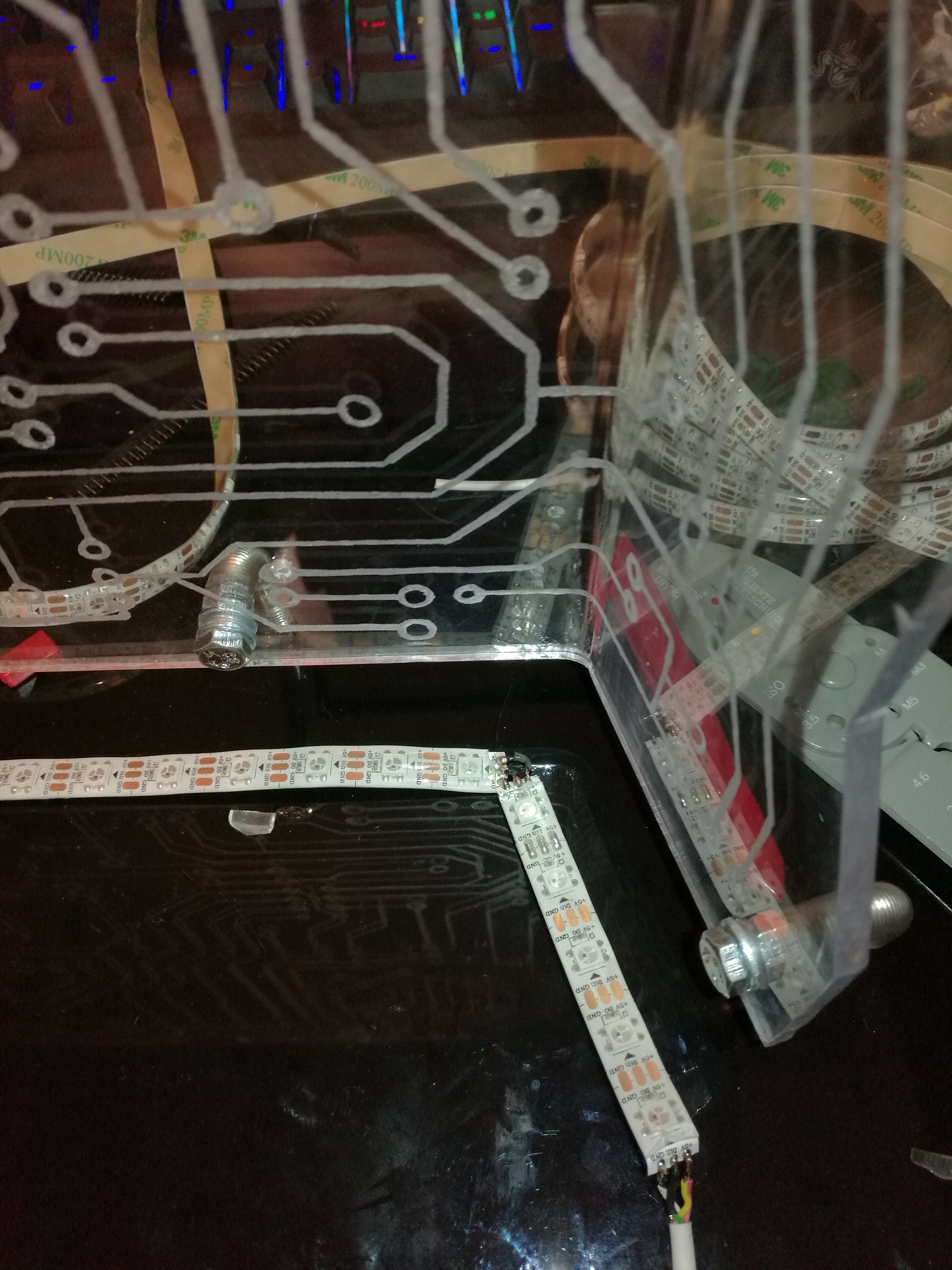
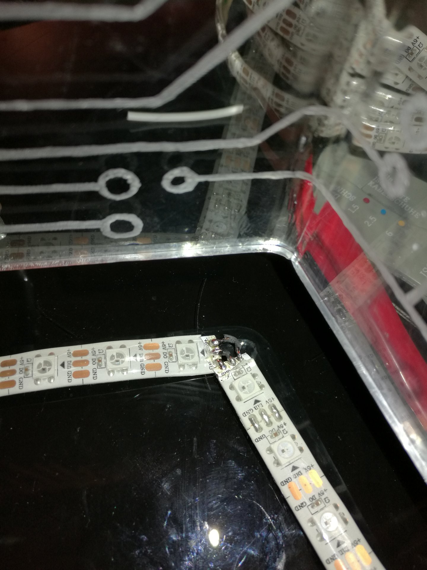
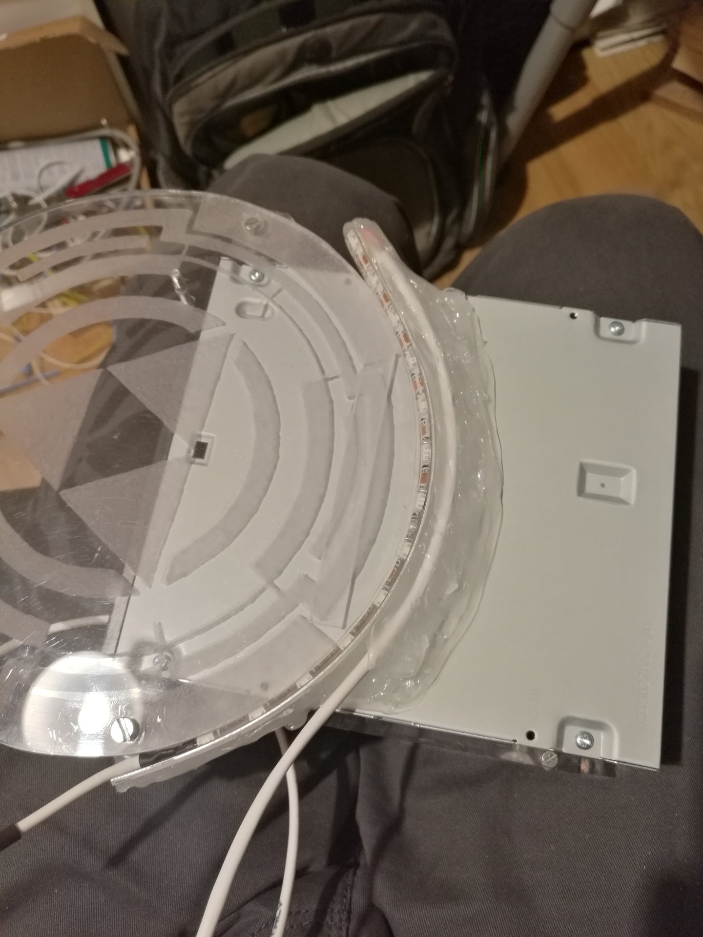
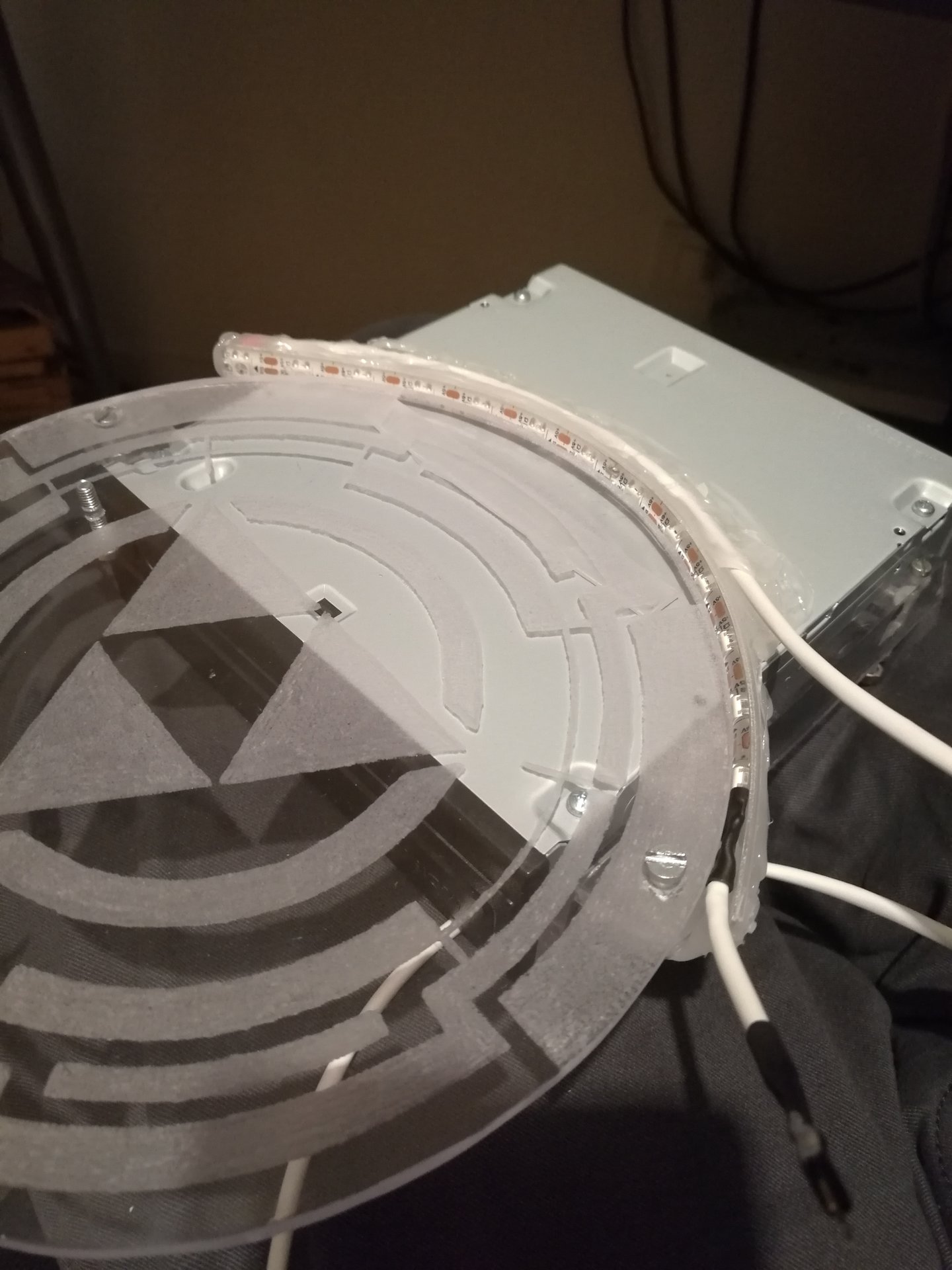
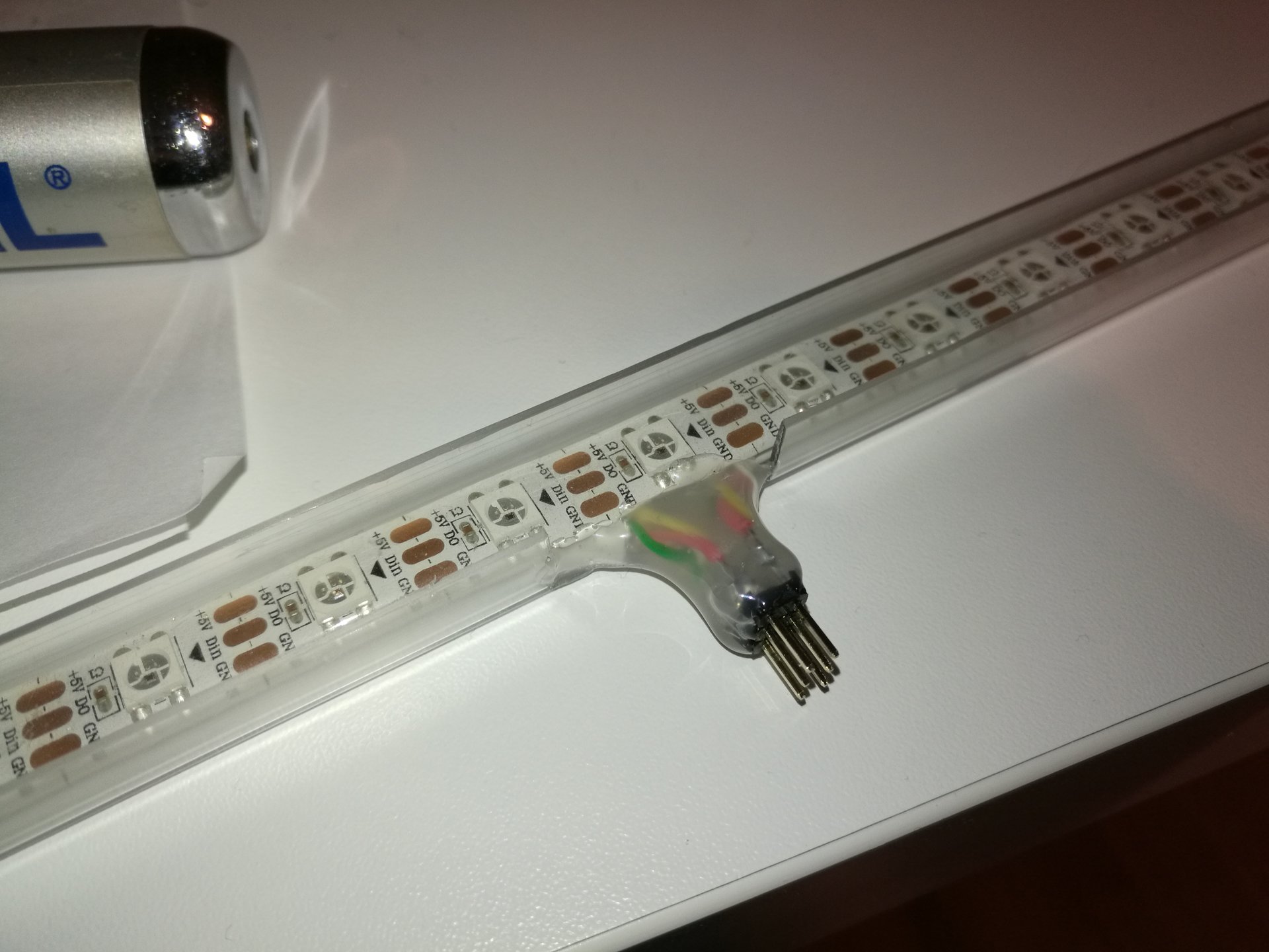
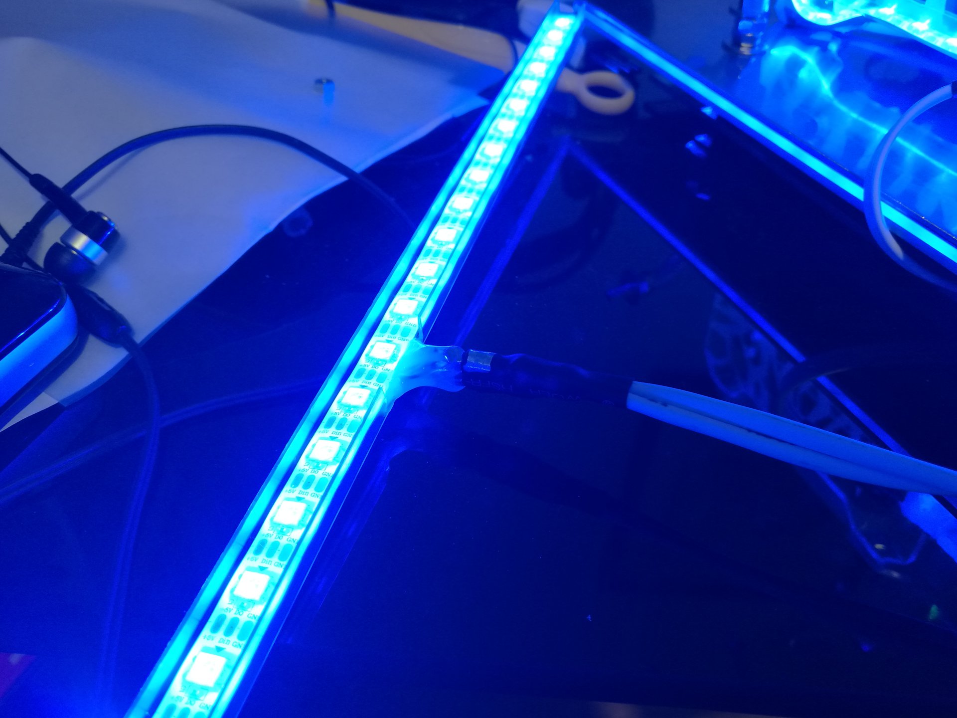
meanwhile I soldered wires and connectors on each led strip end (all the strip pieces are connected in series, so each piece must have an entering cable and an exiting cable):
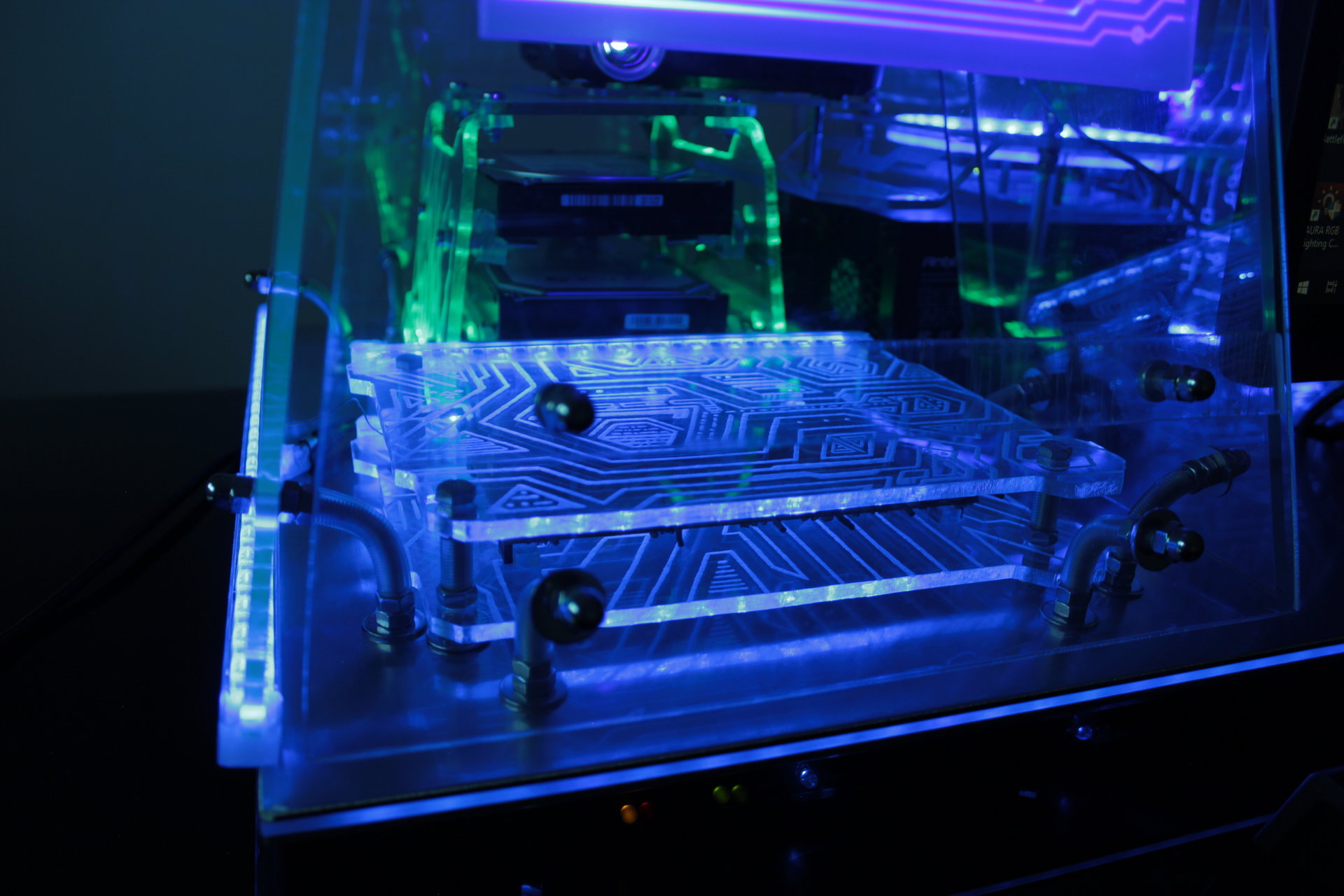
I soldered an angled led strip for the motherboard support:
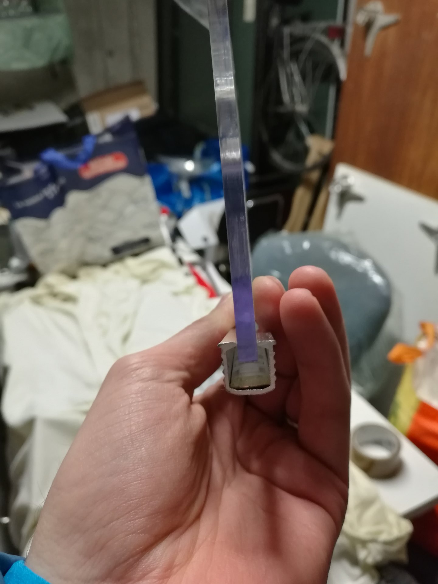
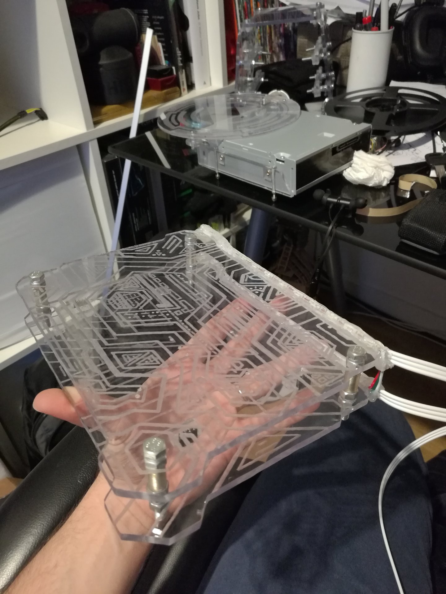
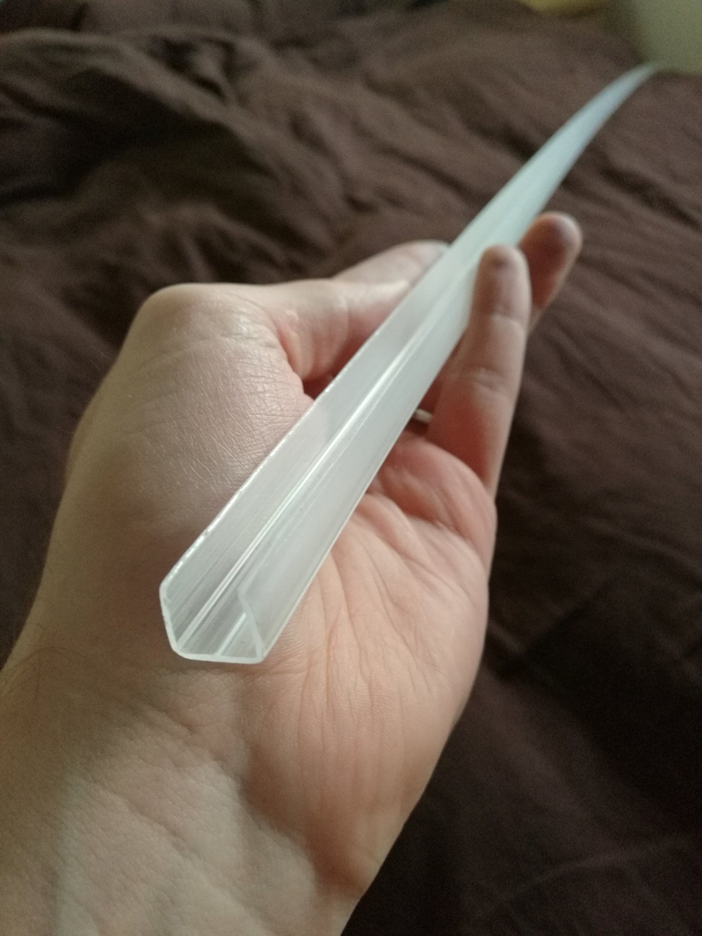
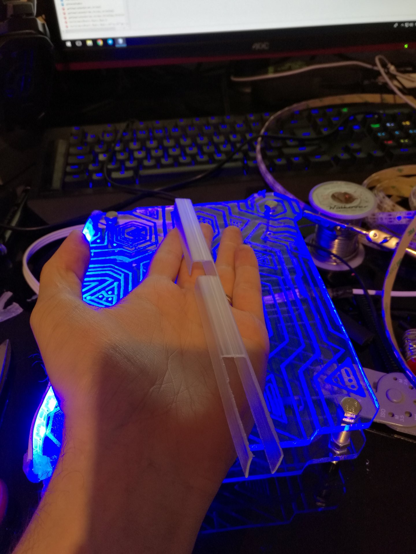
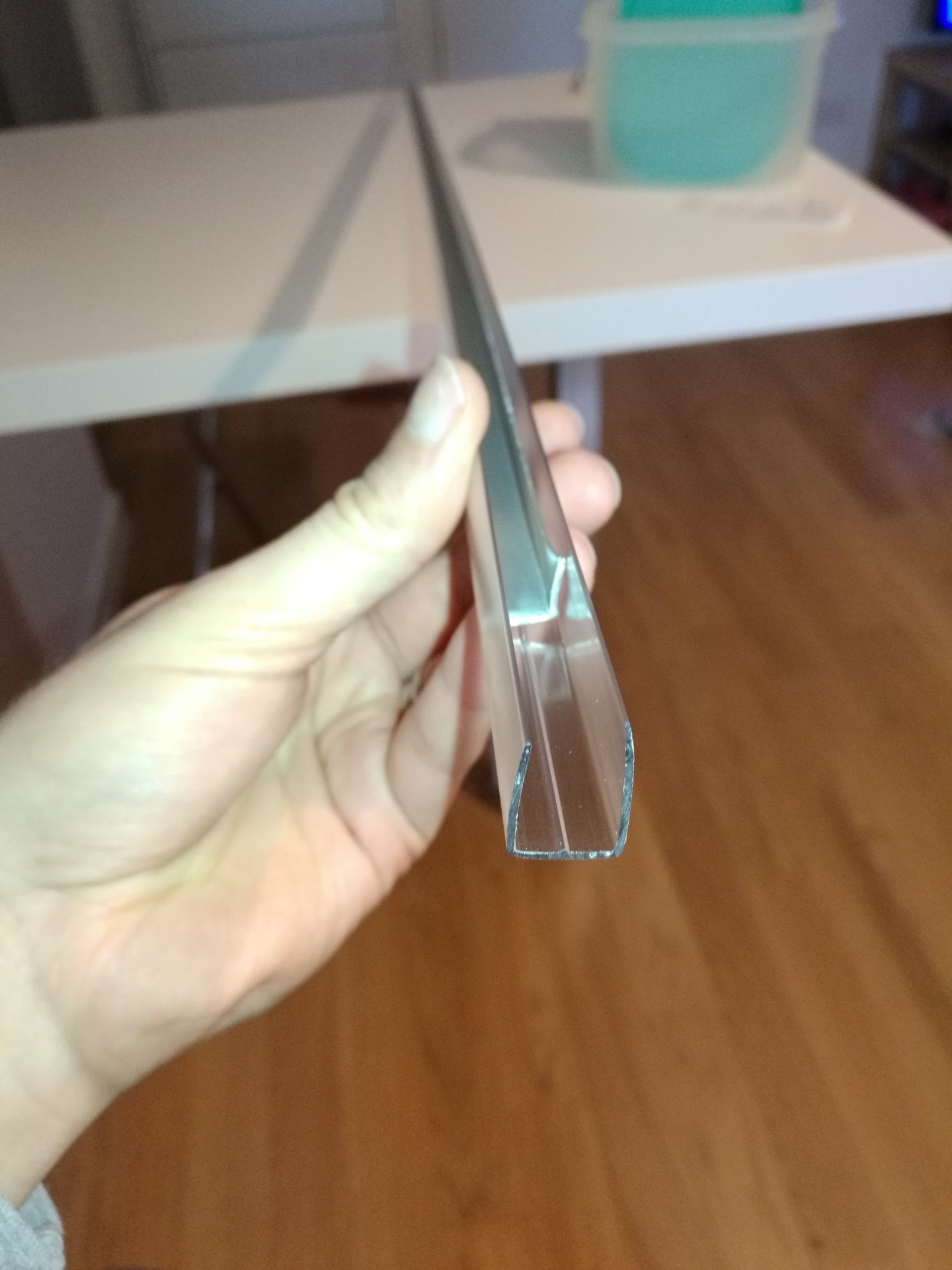
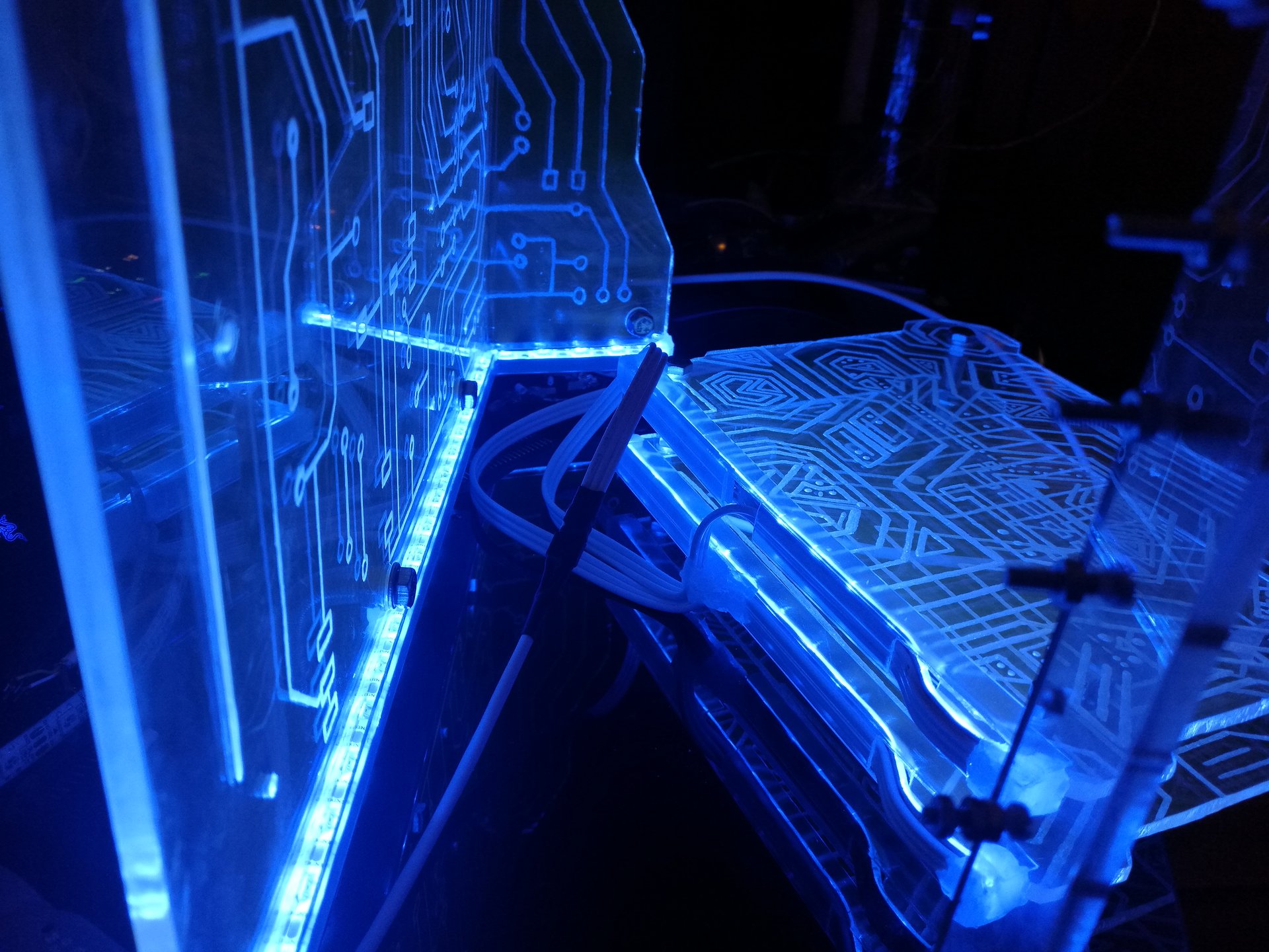
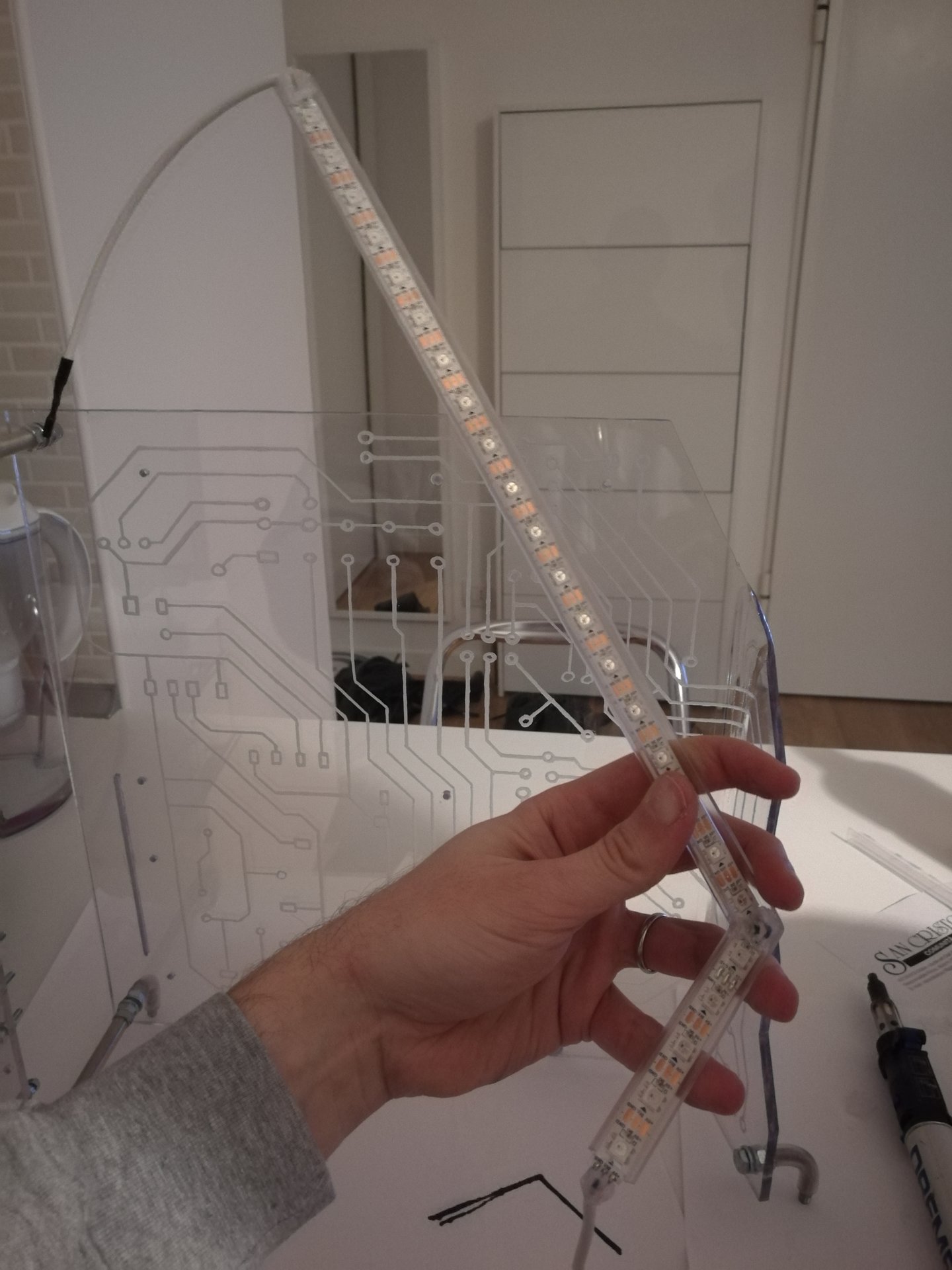
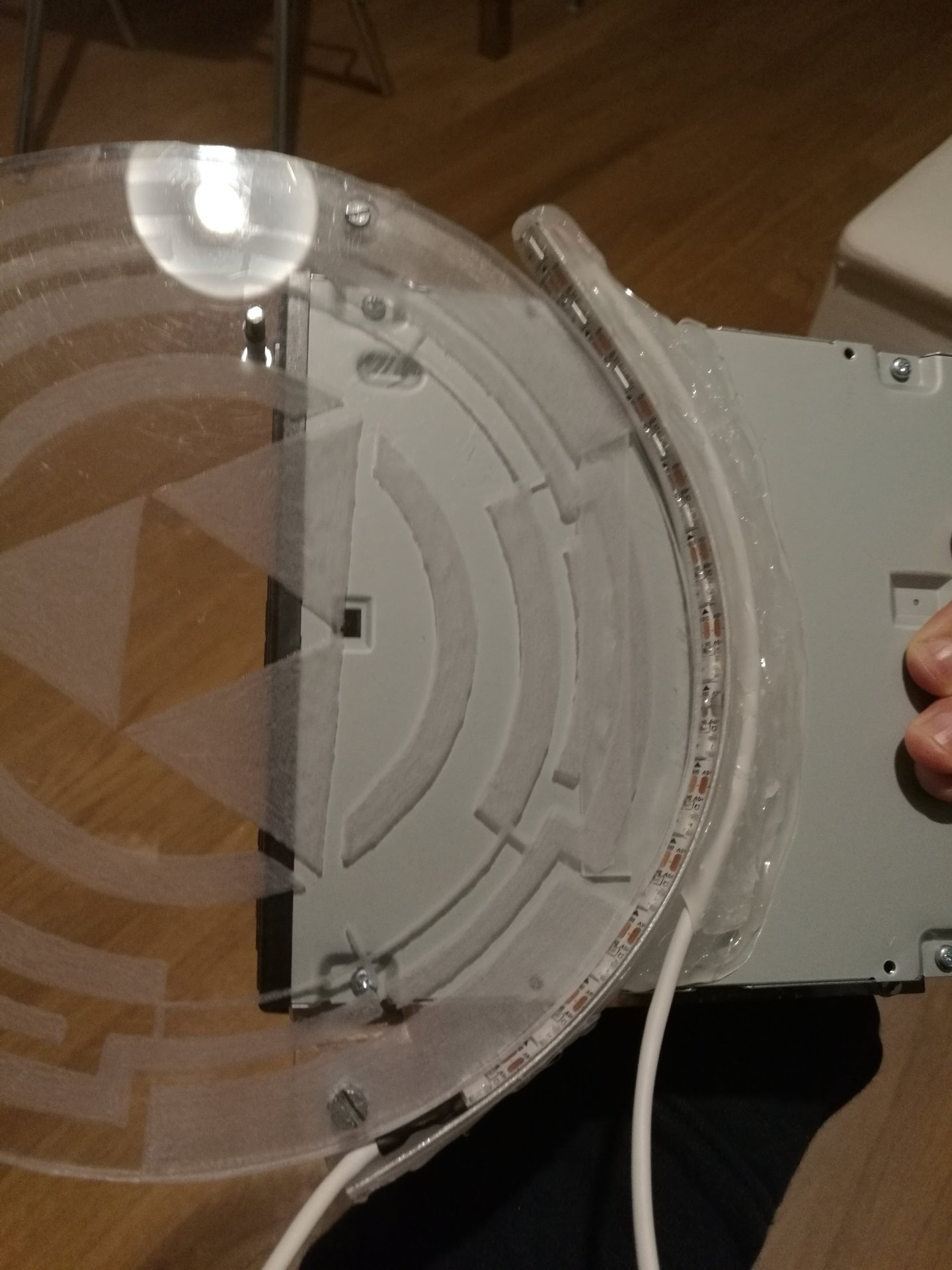
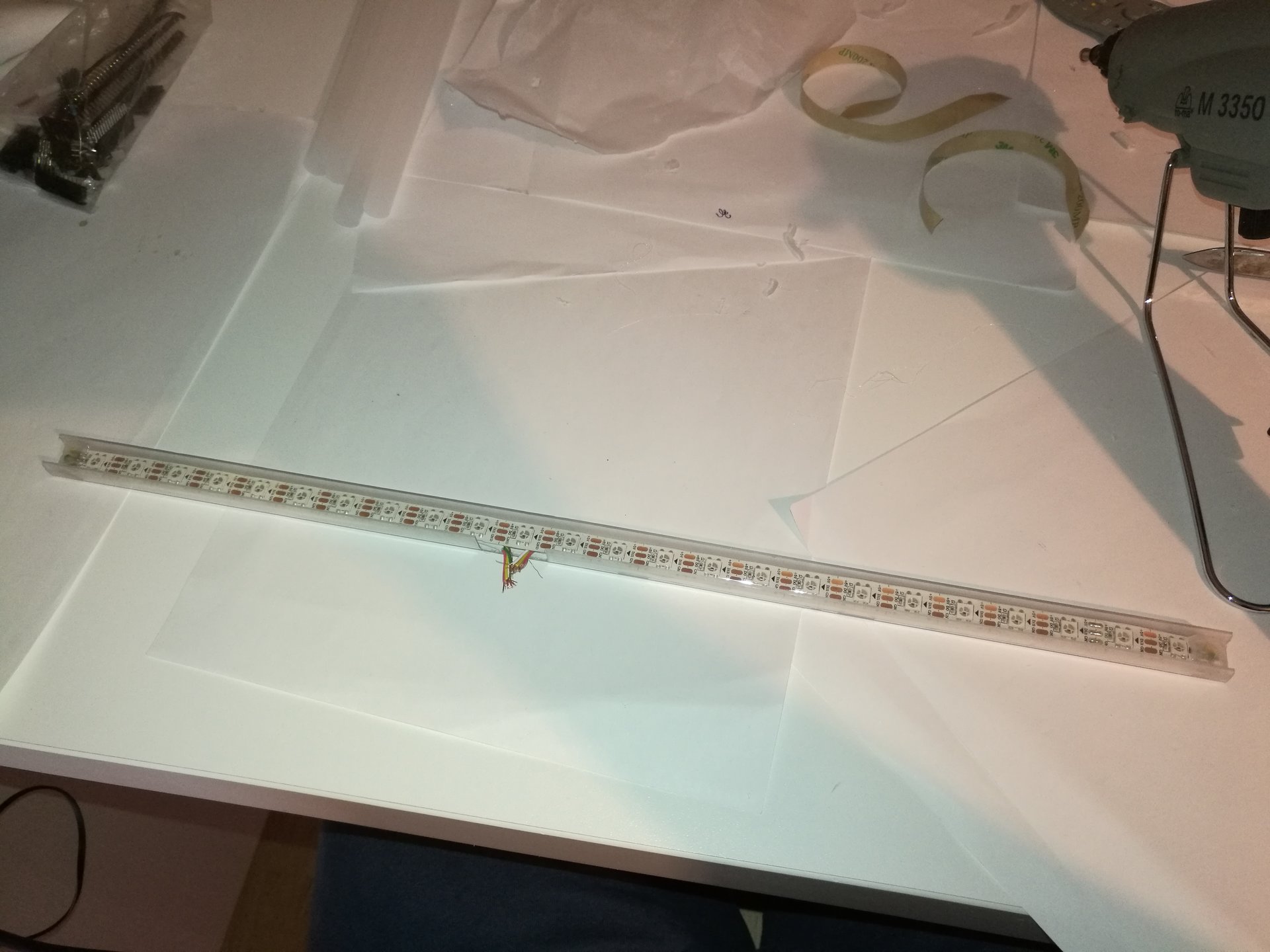
another try to keep in place the led strips: I used a transparent polycarbonate U profile, and I sanded it:
The result was good, but only after finishing this try I thought that it could be better if I use it trasparent, without sanding it:
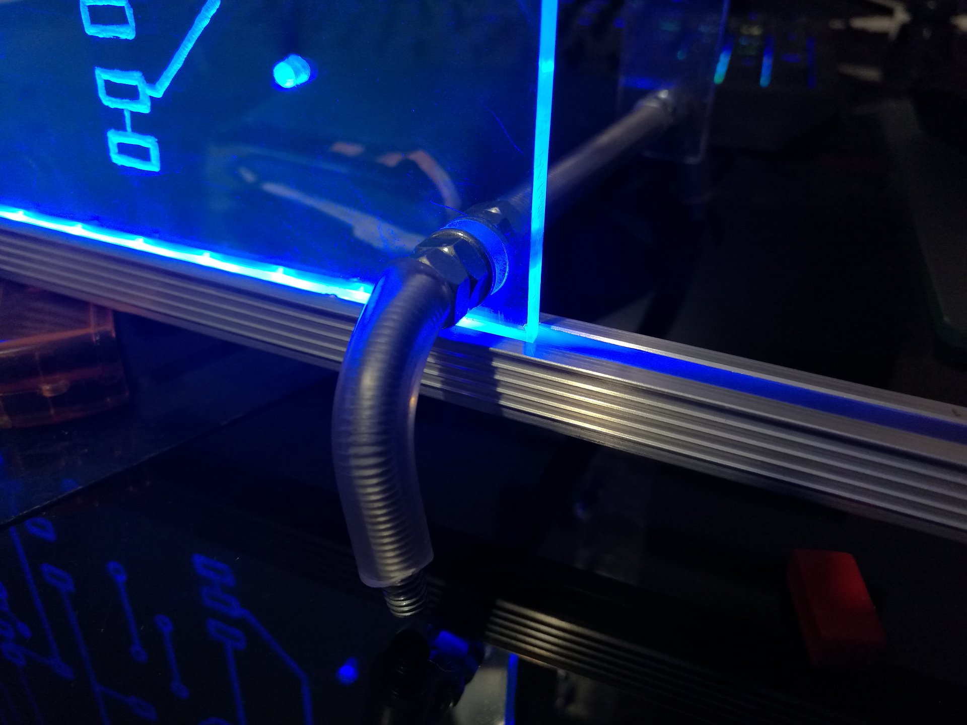
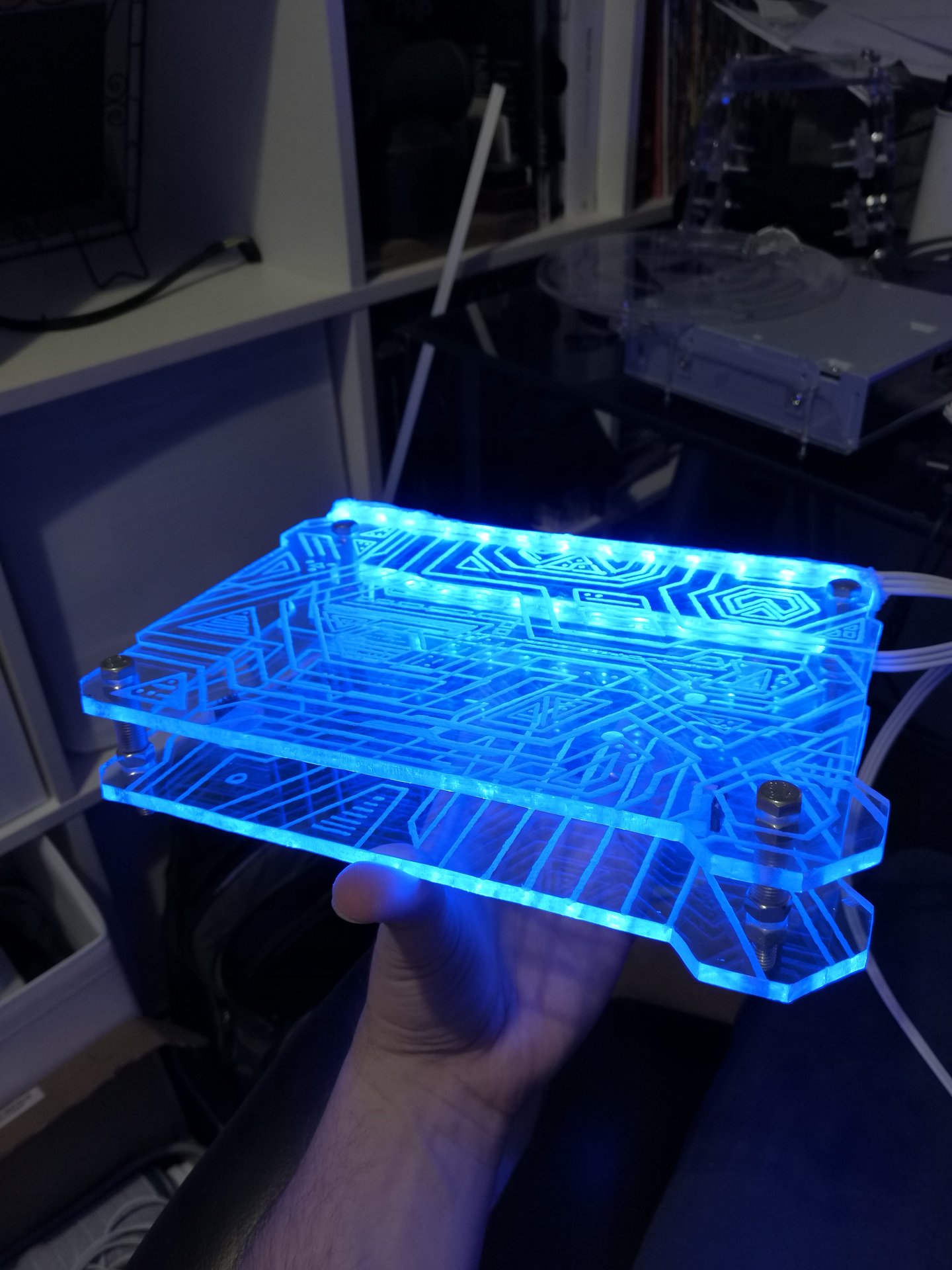
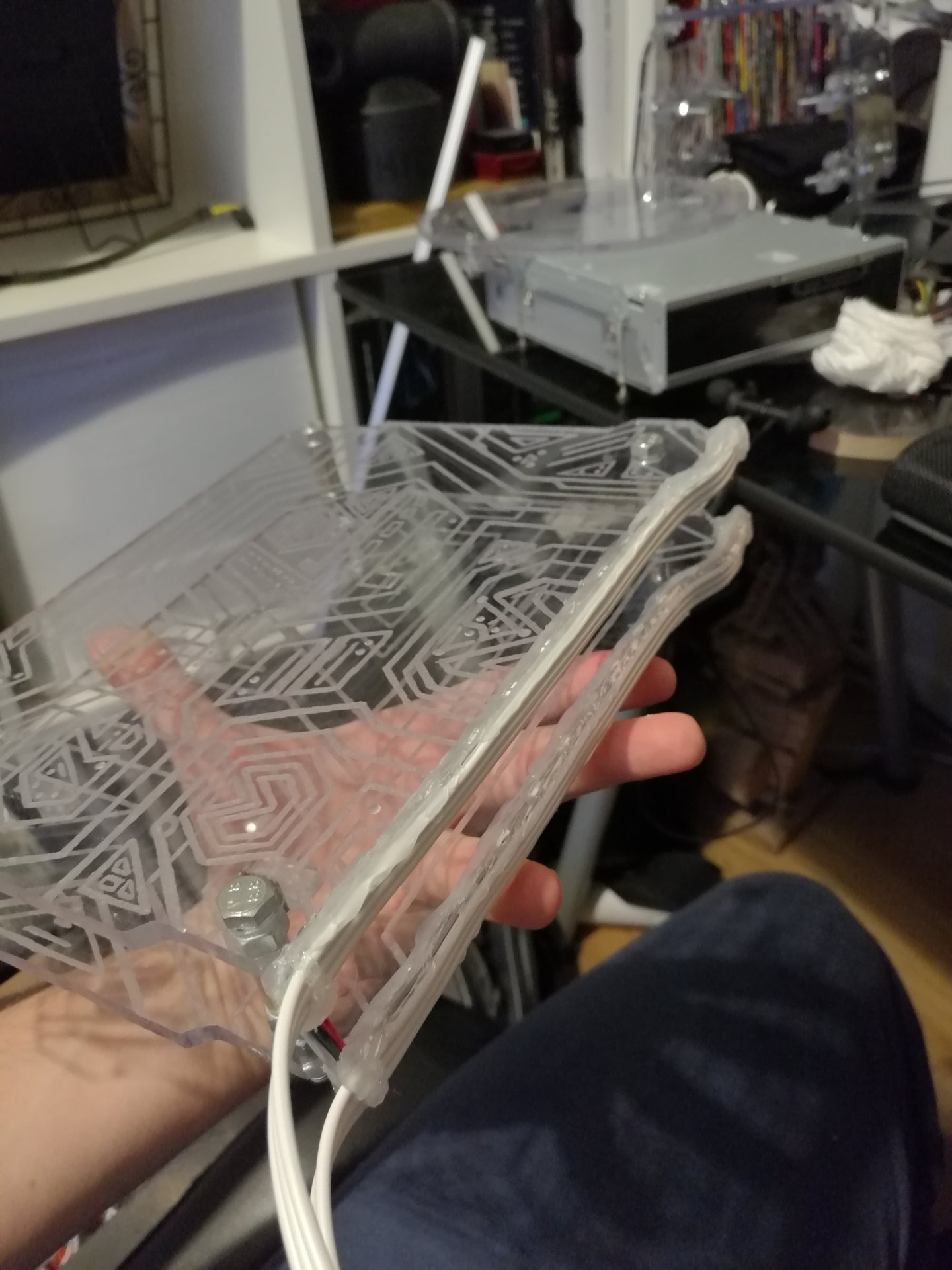
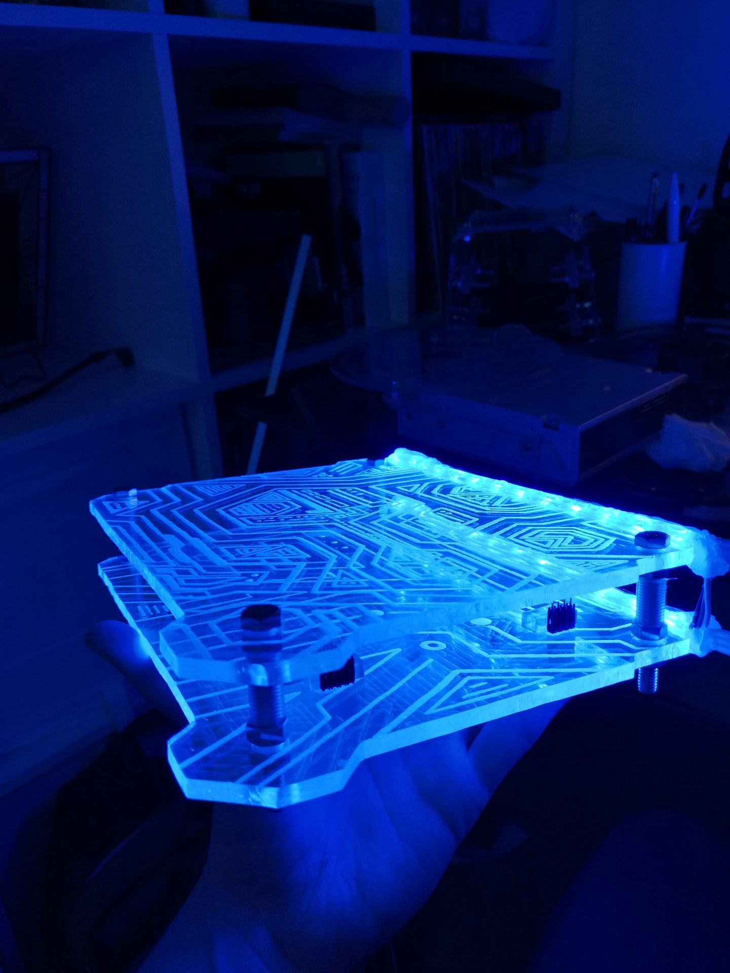
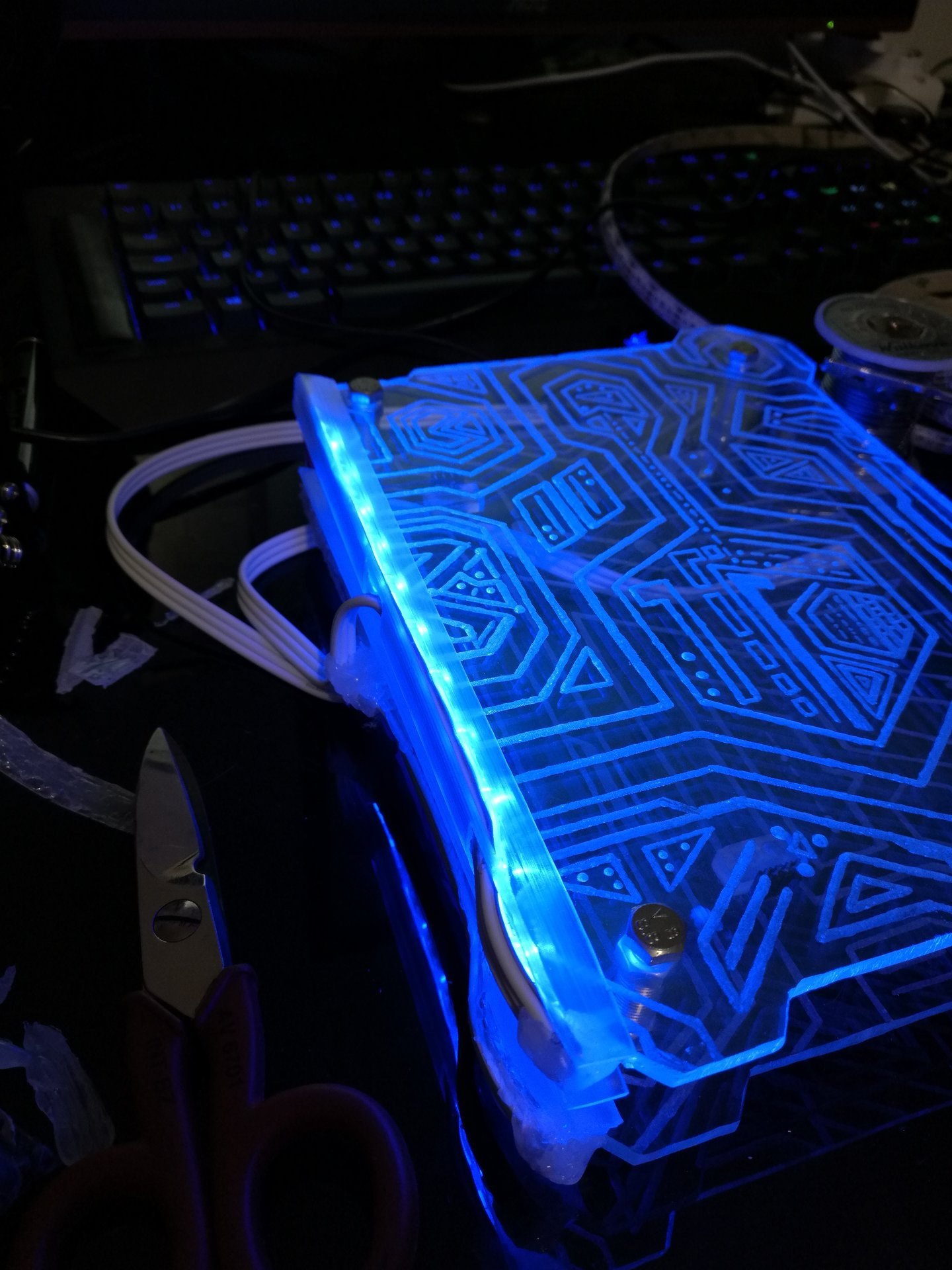
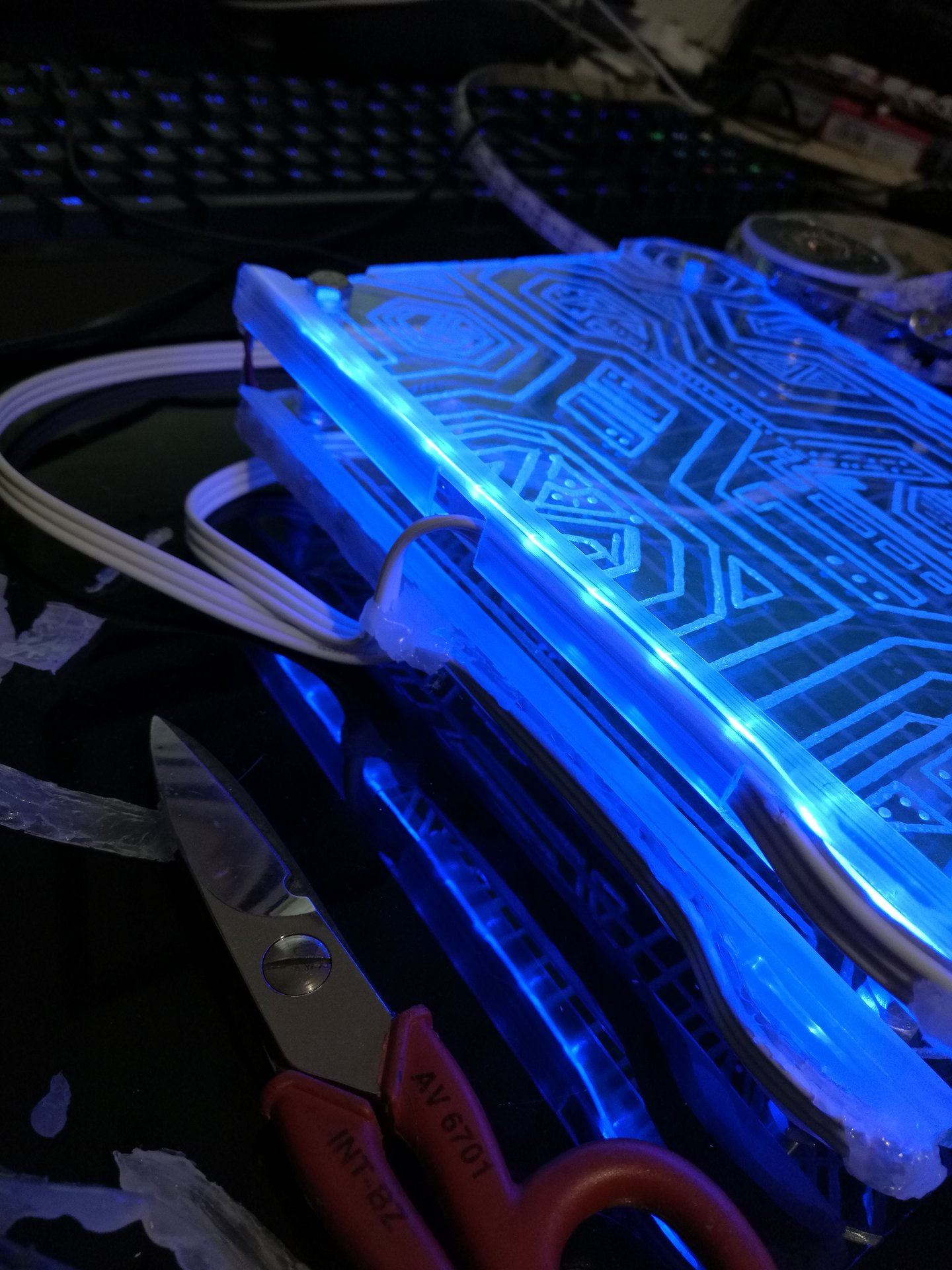
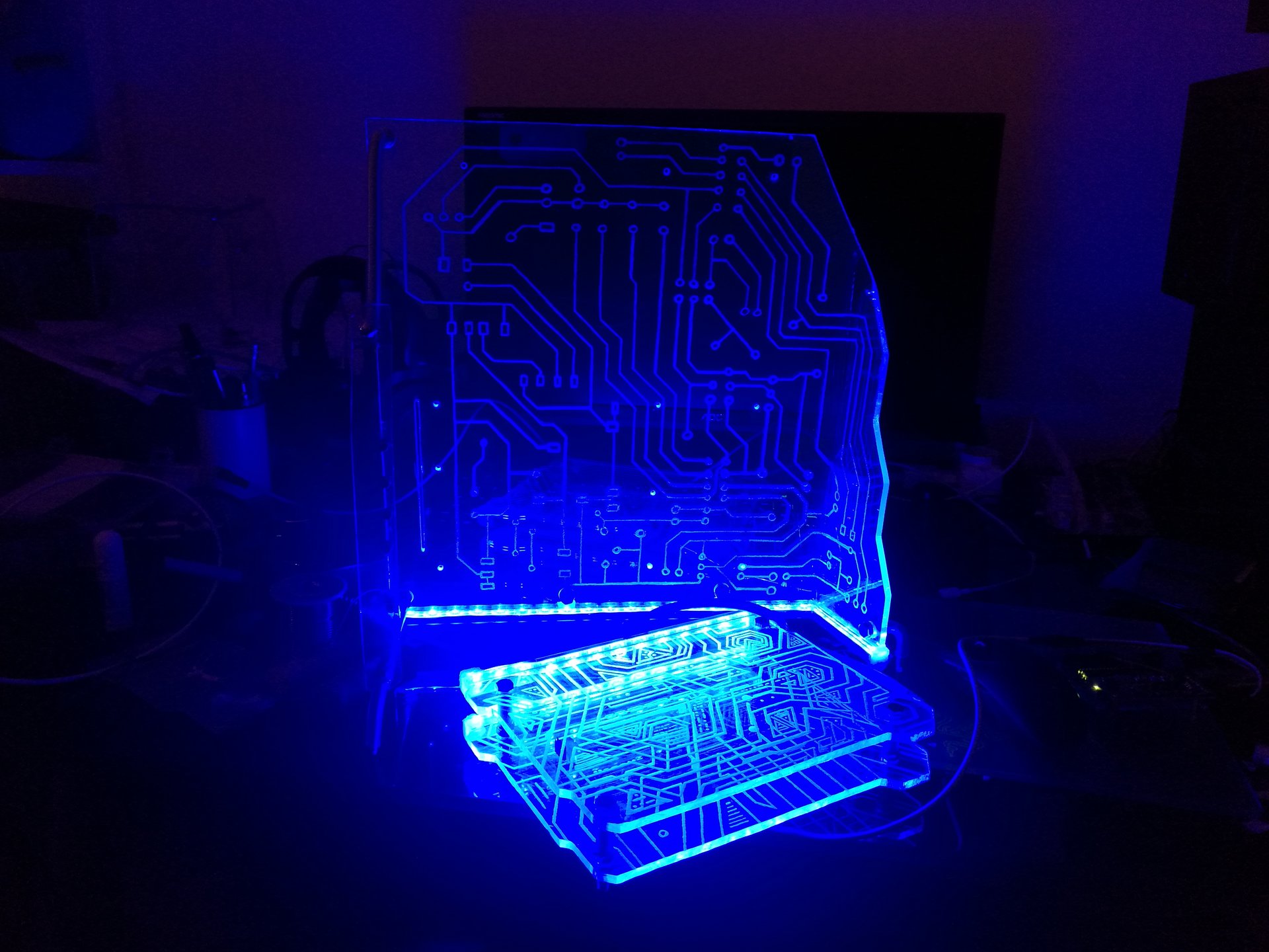
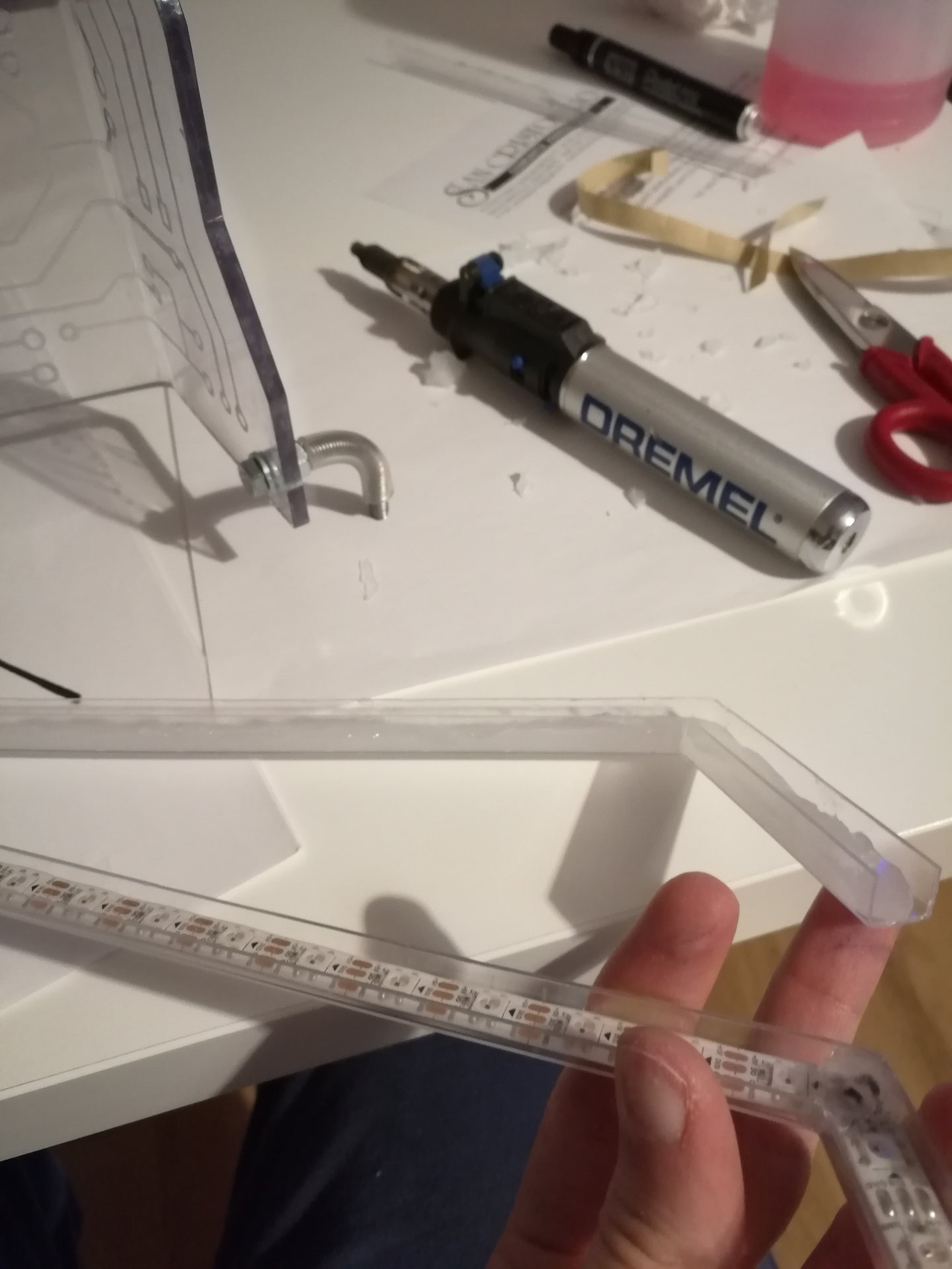
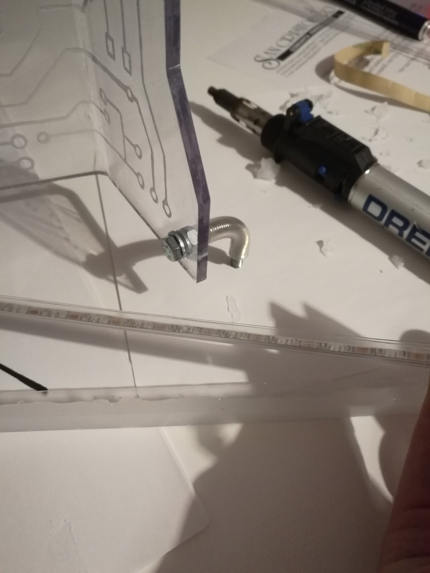
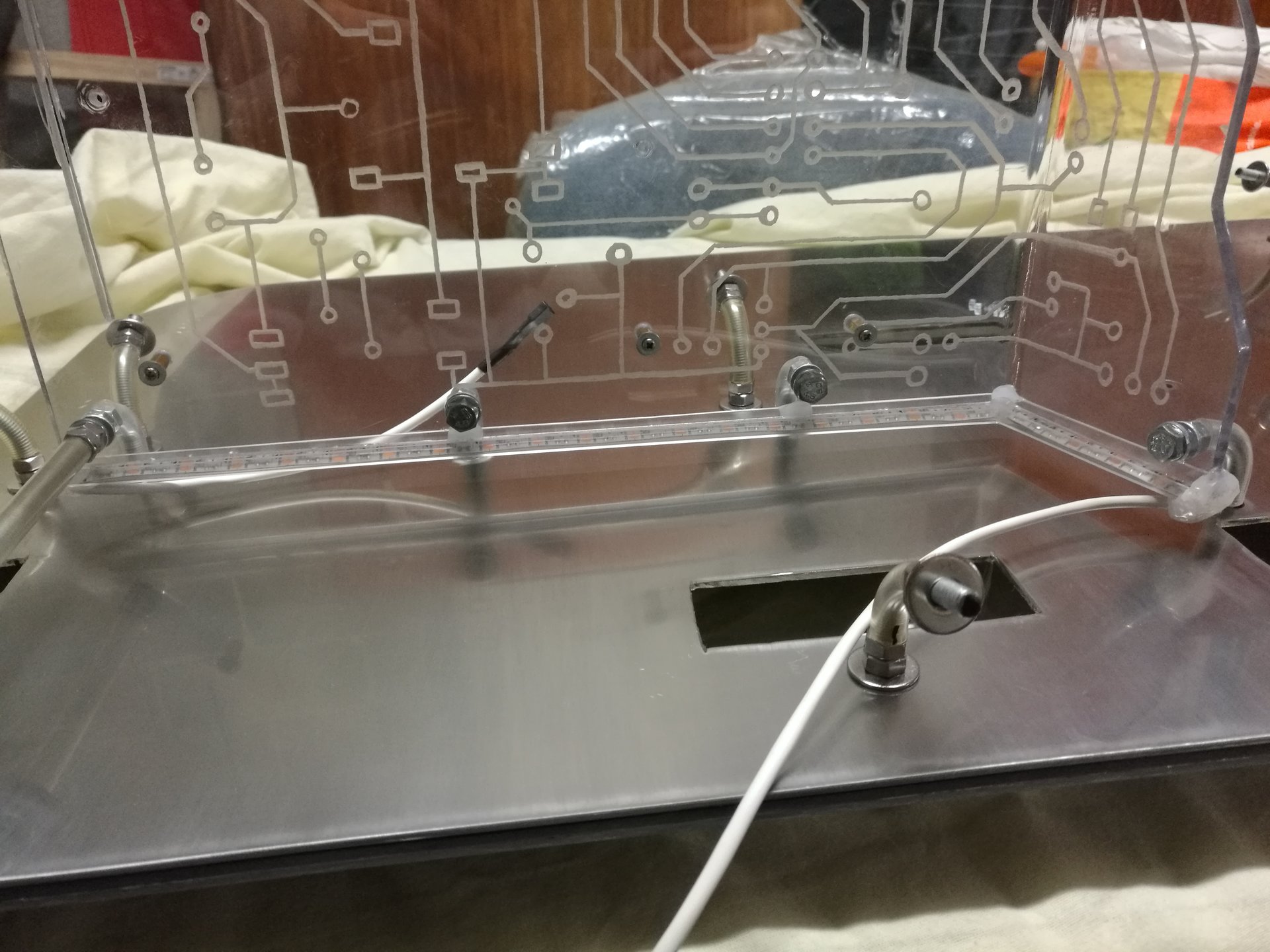
I have done this last try with the trasparent not-sanded U profile, and finally I have found the best solution! 😀
Then I remade from scratch the U profile under the motherboard structure, because the first one that I made was too high and I ruined it with the hot glue:
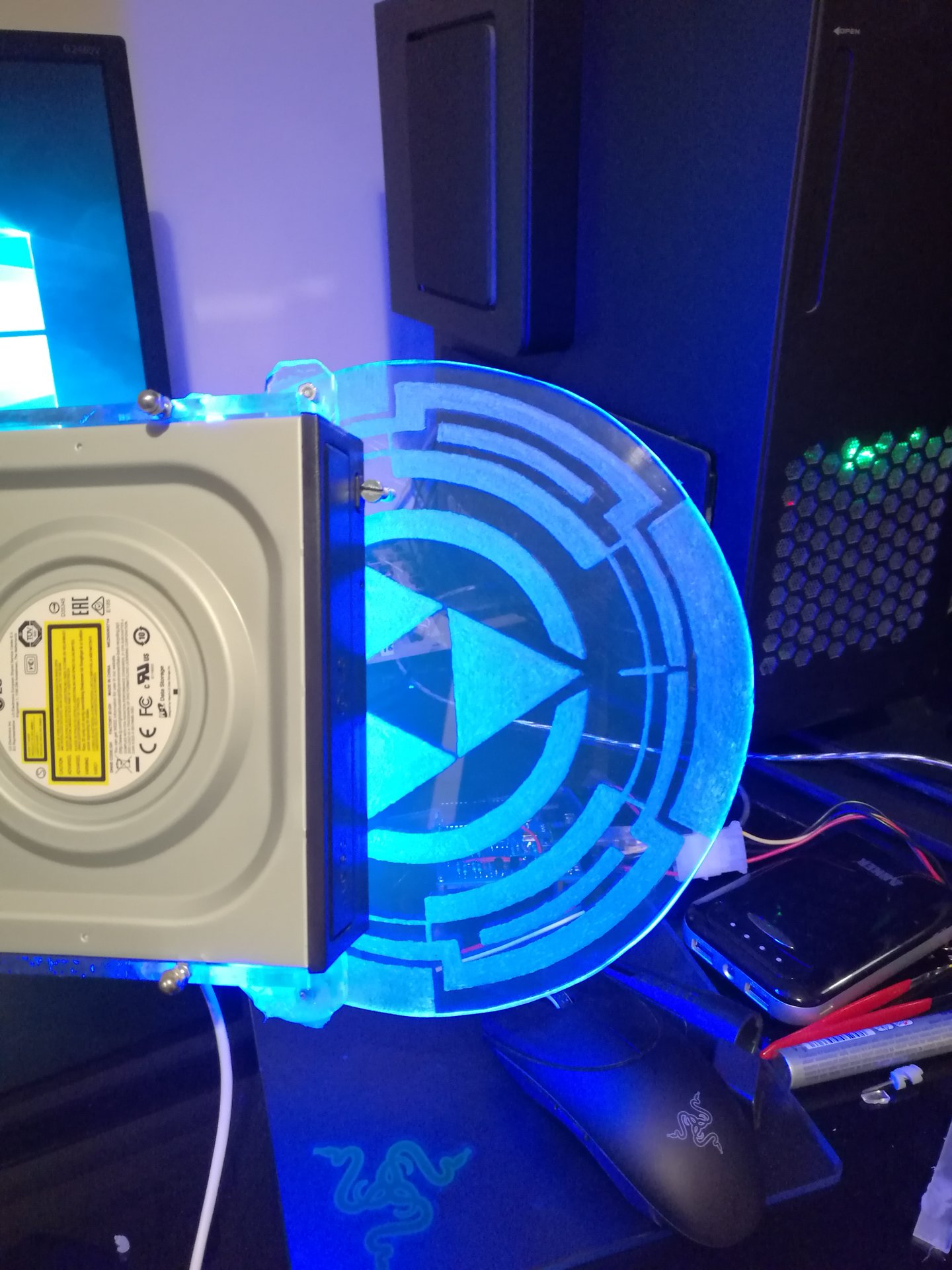
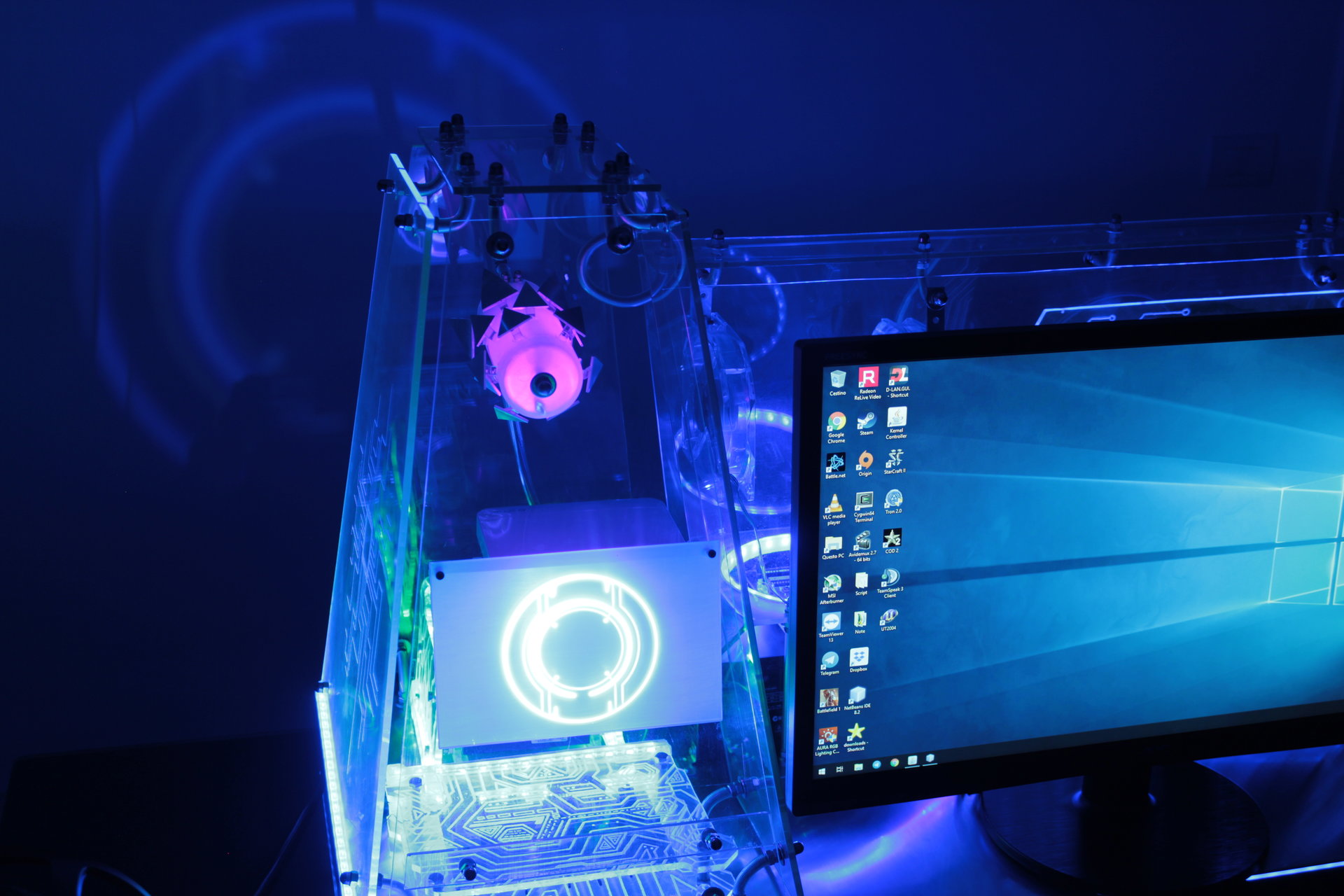
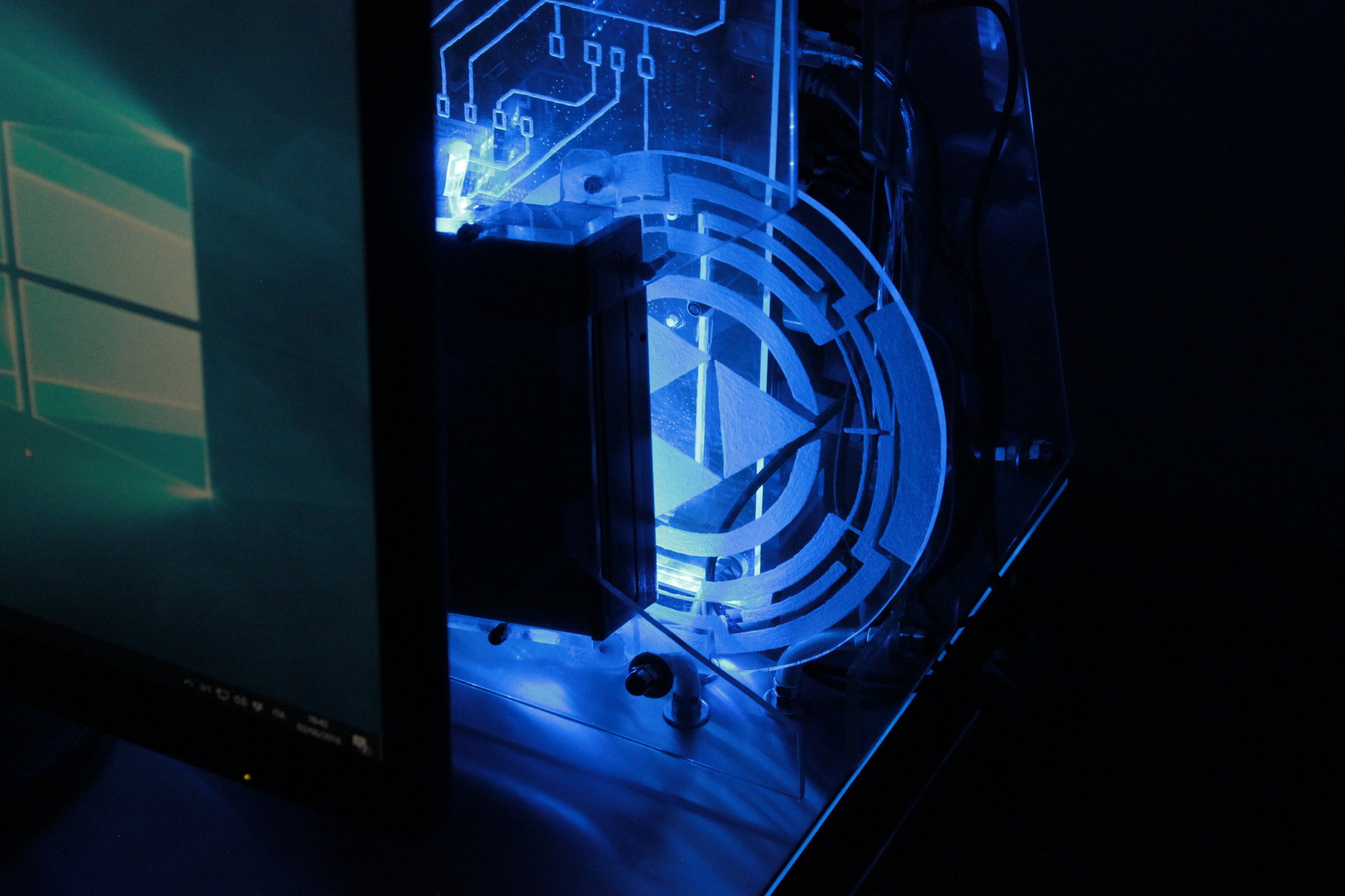
And finally I have glued a led strip behind the optical drive structure, to enlight the “Tron disc” (the optical drive button):
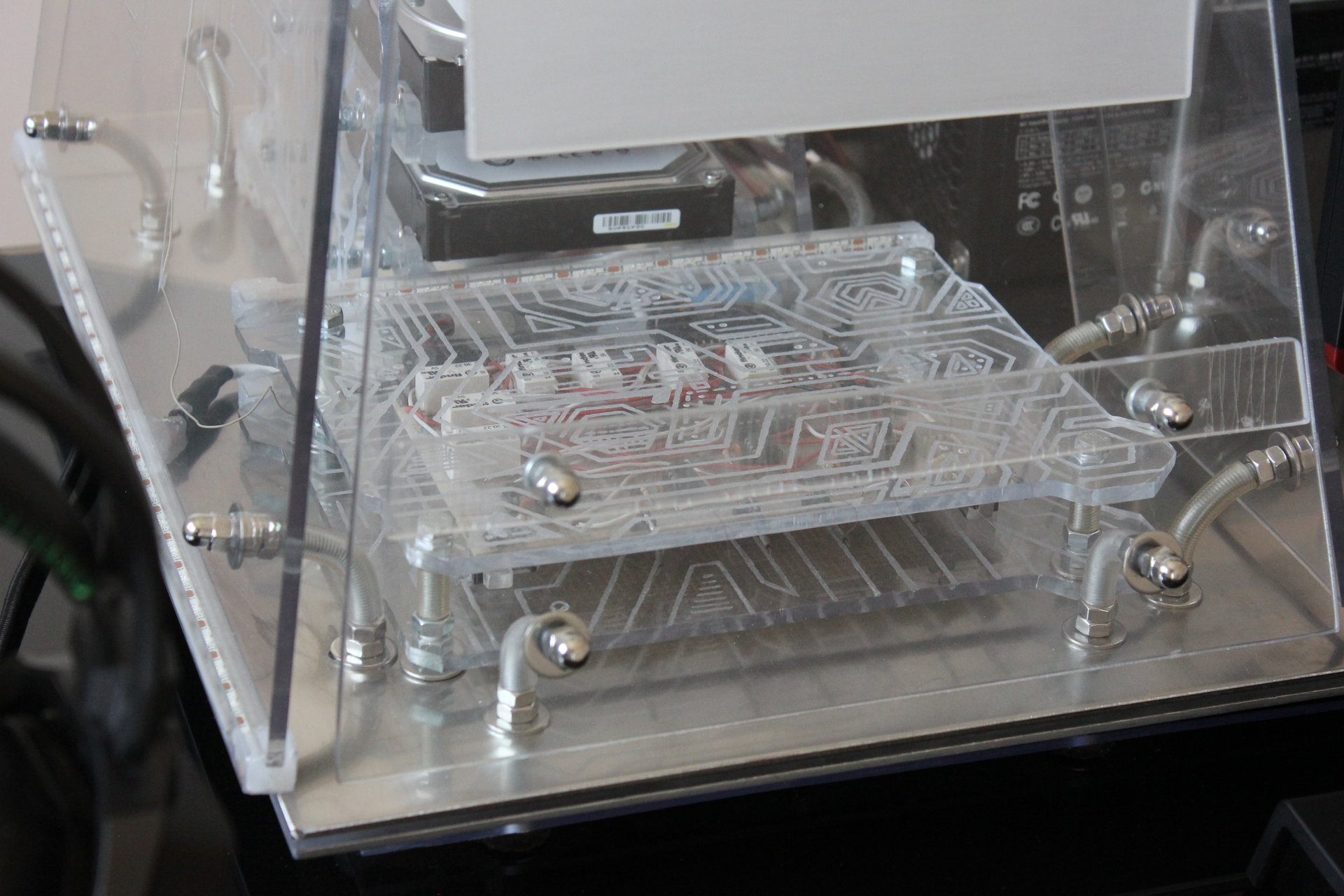
After working on the led strips I have mounted the motherboard standoffs on the motherboard structure:
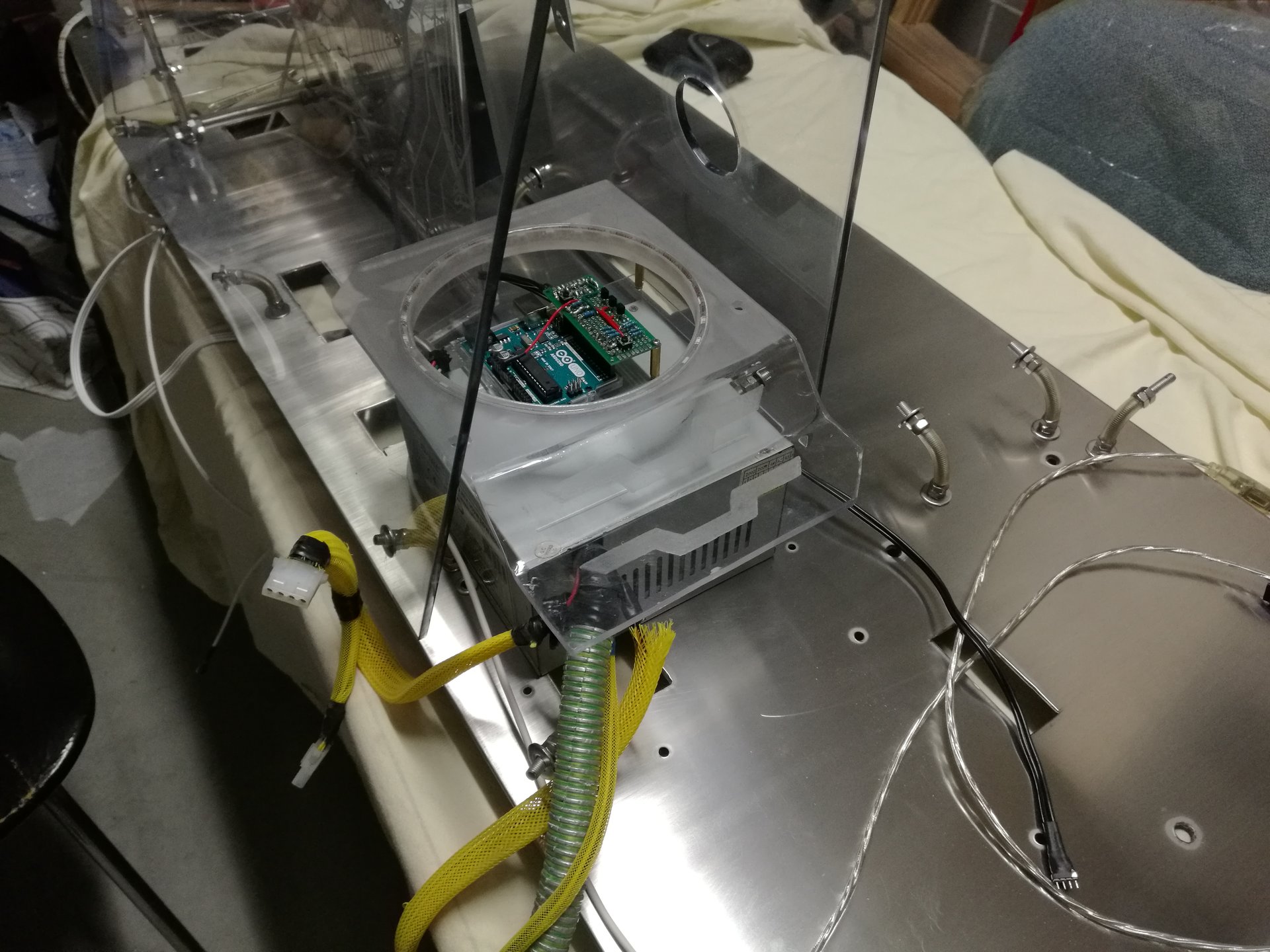
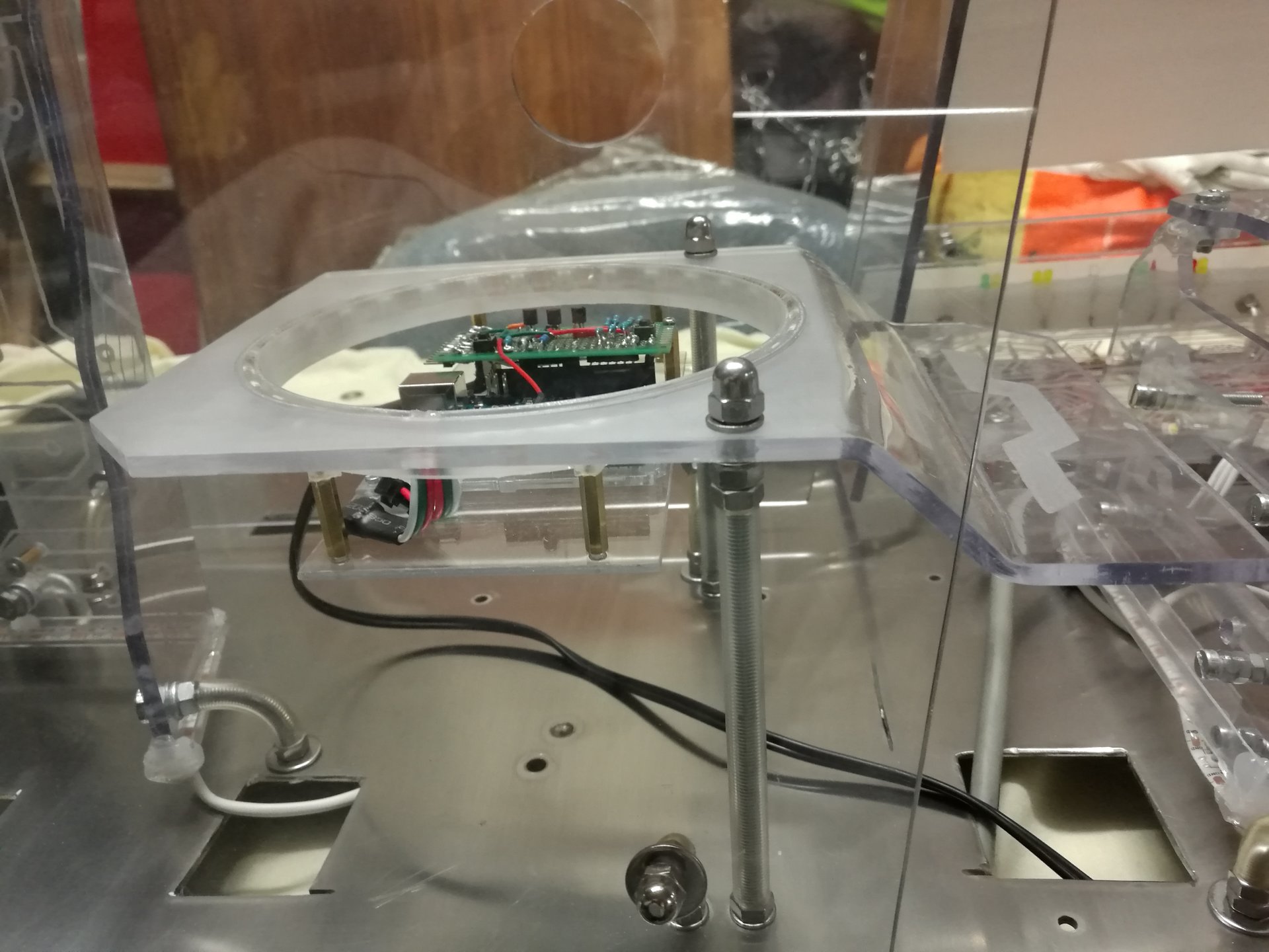
Then I have started working on a new component: the Arduino encasing structure.
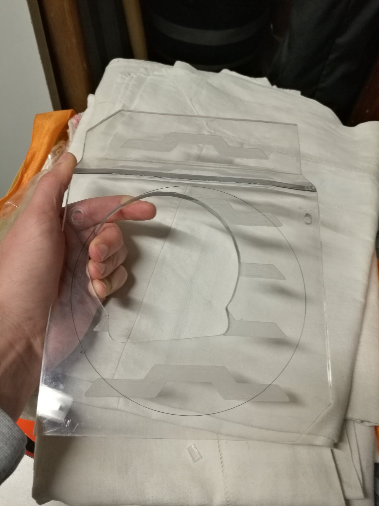
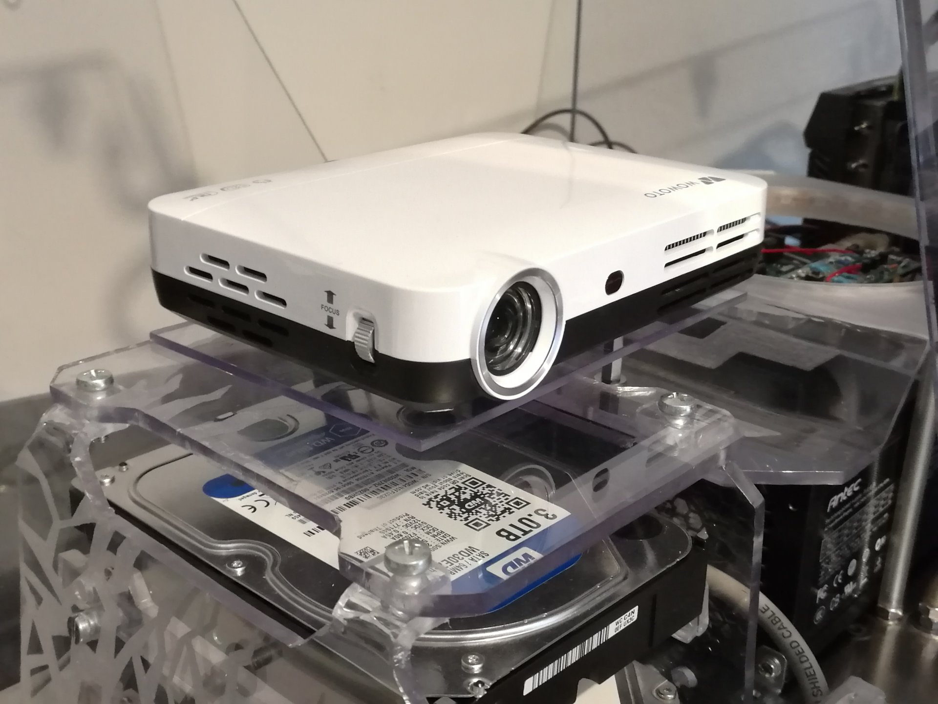
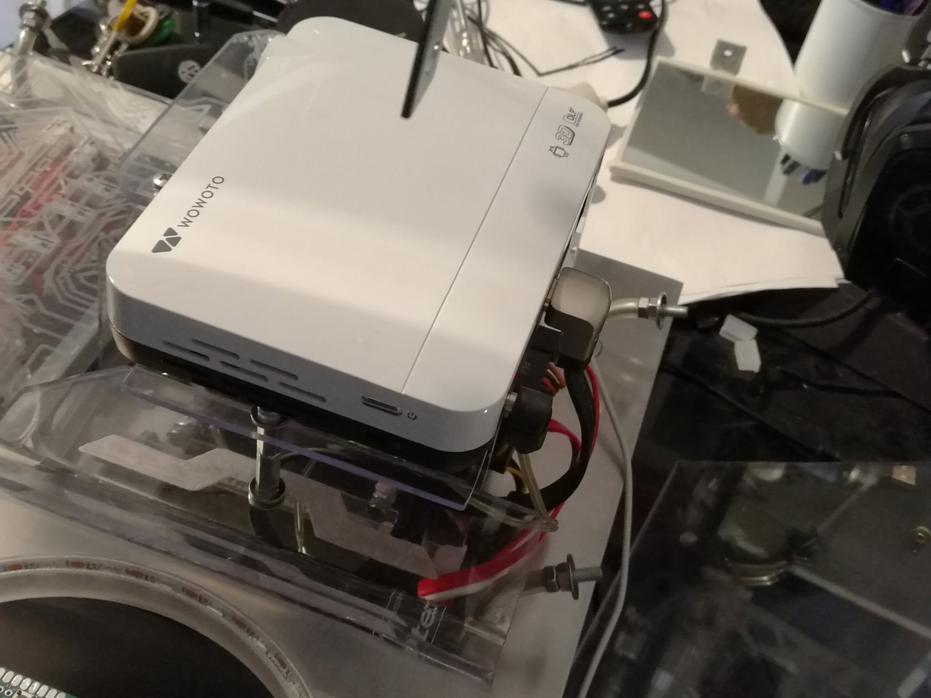
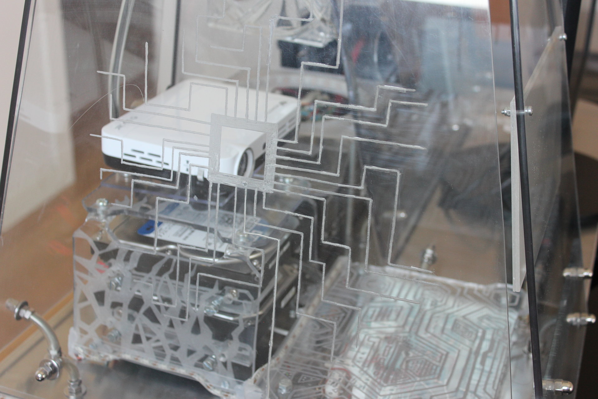
The base for this structure is the old “PSU cover/projector holder”, that I modified radically because I changed the projector, and the new projector has a different size and position in the case, so the old PSU cover is useless now.
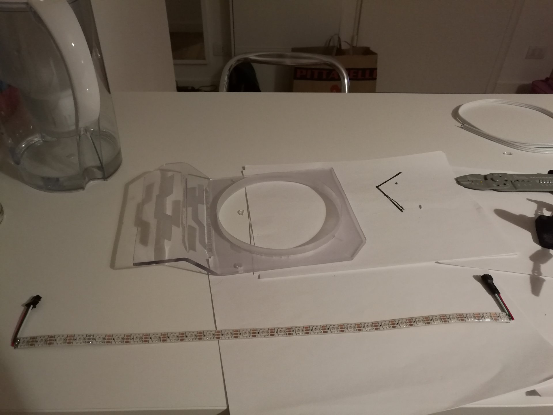
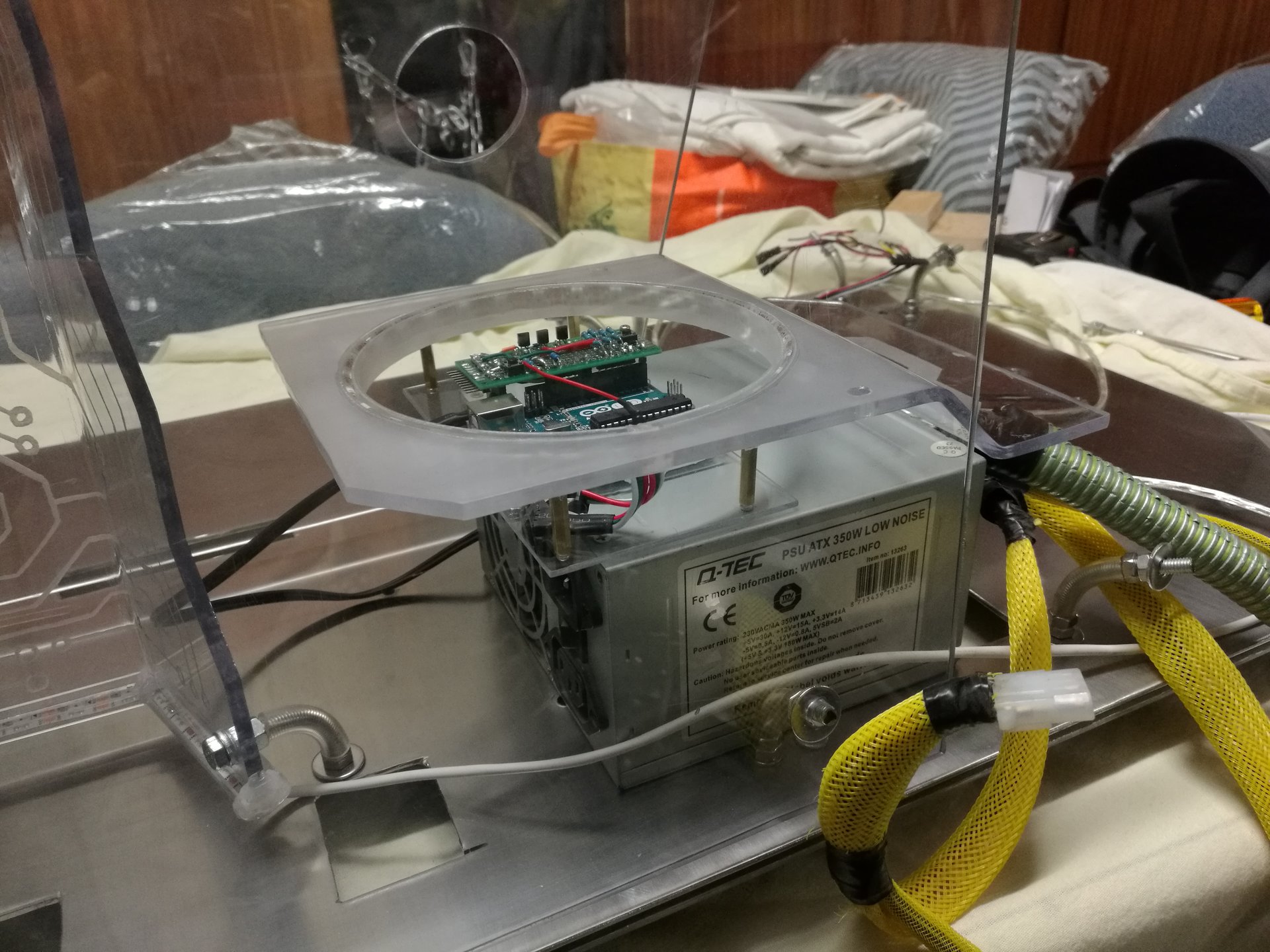
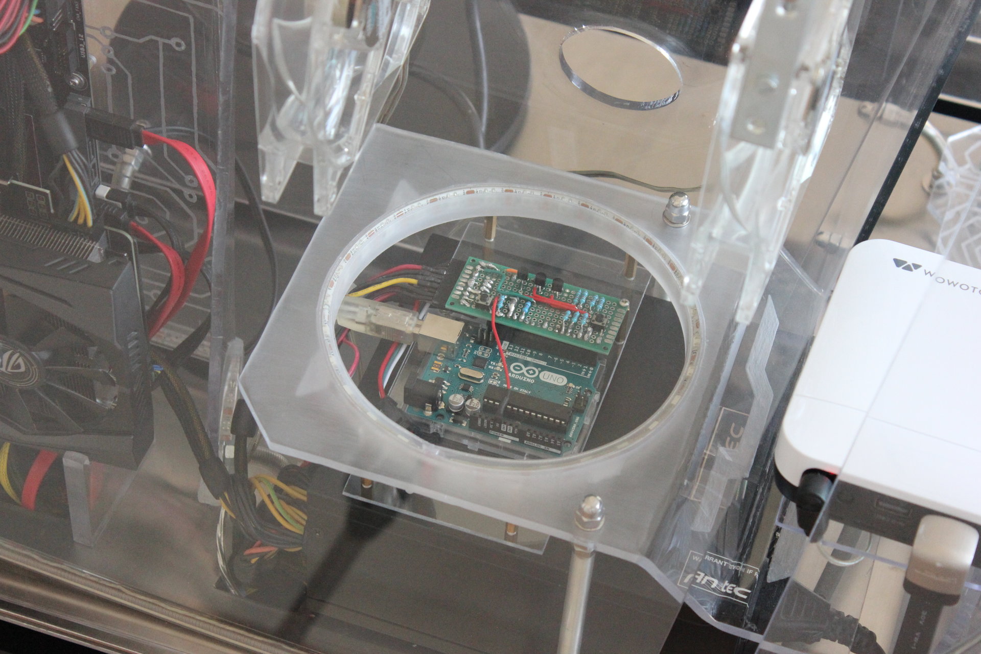
My idea is to make a big round hole at the center of the PSU cover (bigger than the previous hole for the projector), in which I will put the Arduino…
…and the edge of the hole must be lighted by a led strip, to make a “light ring”! 😀
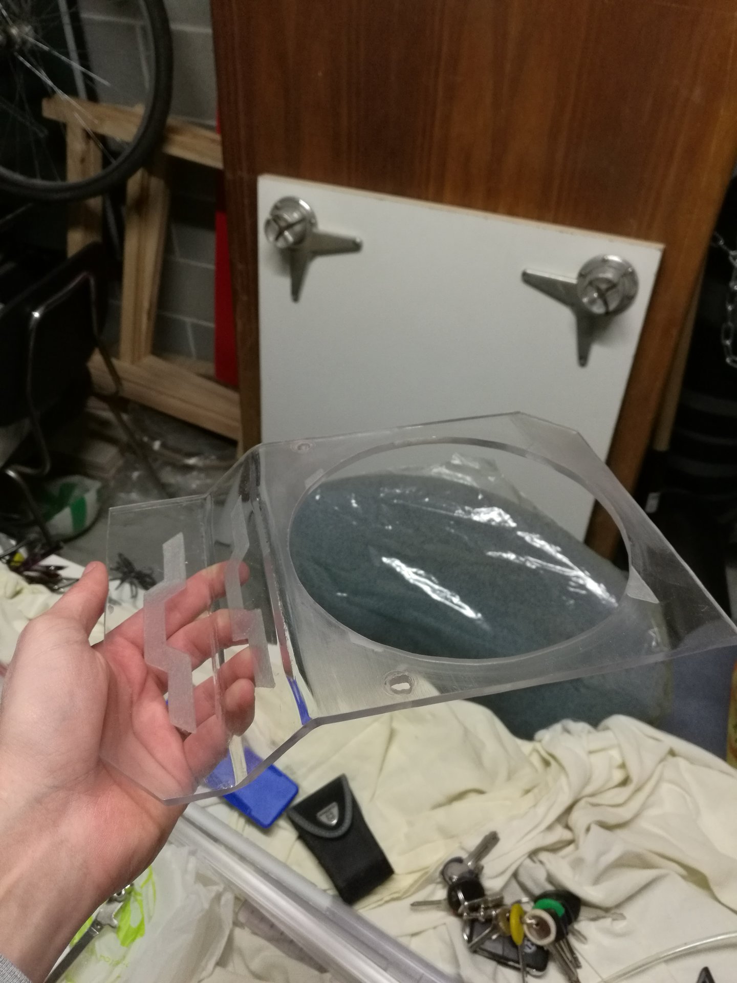
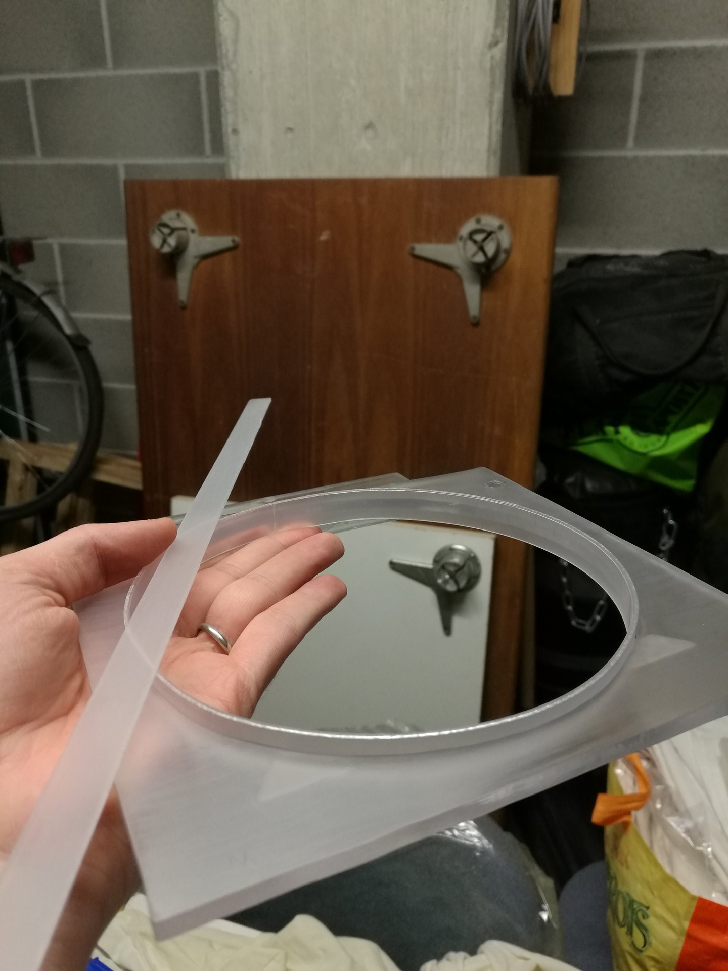
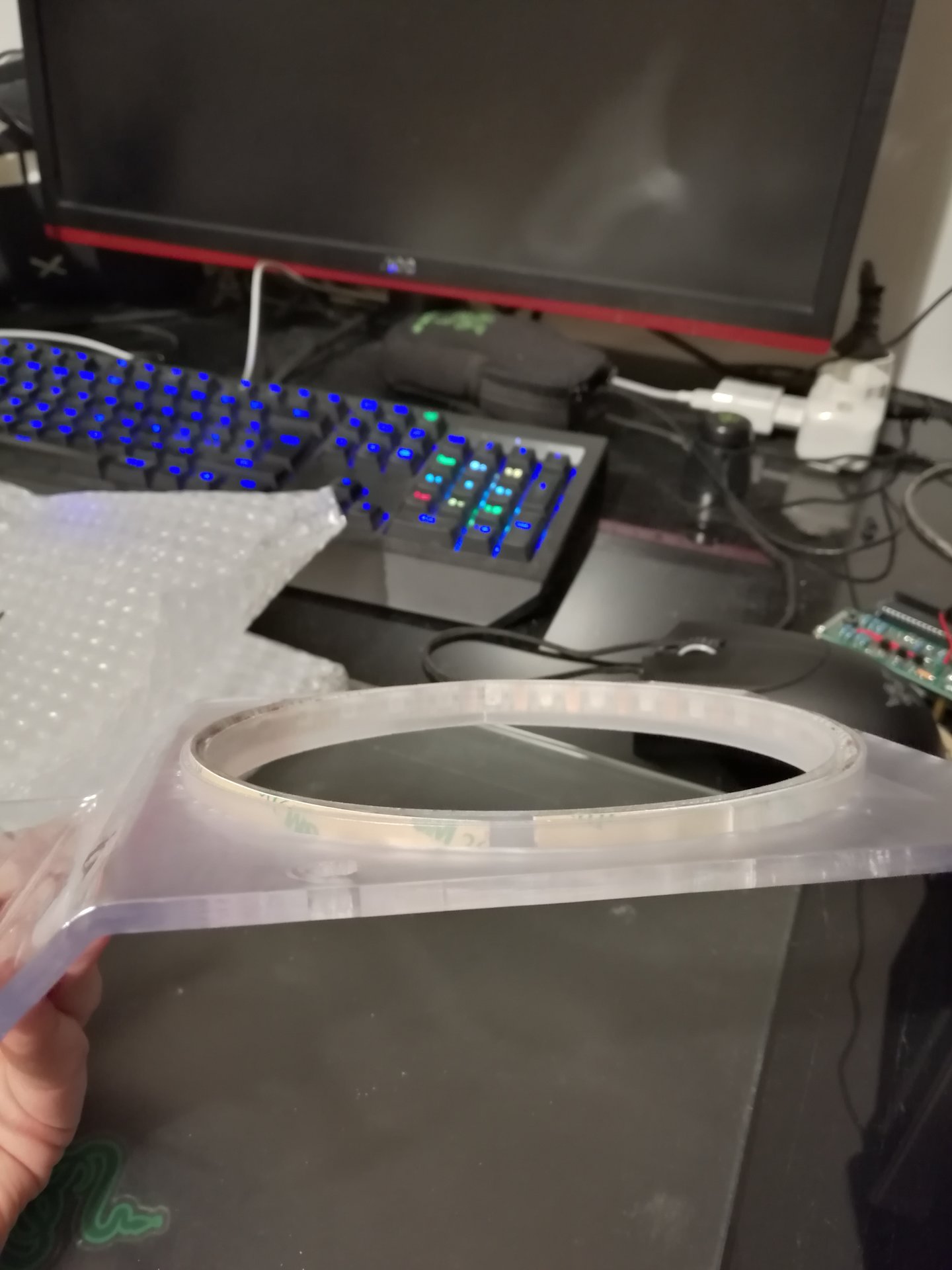
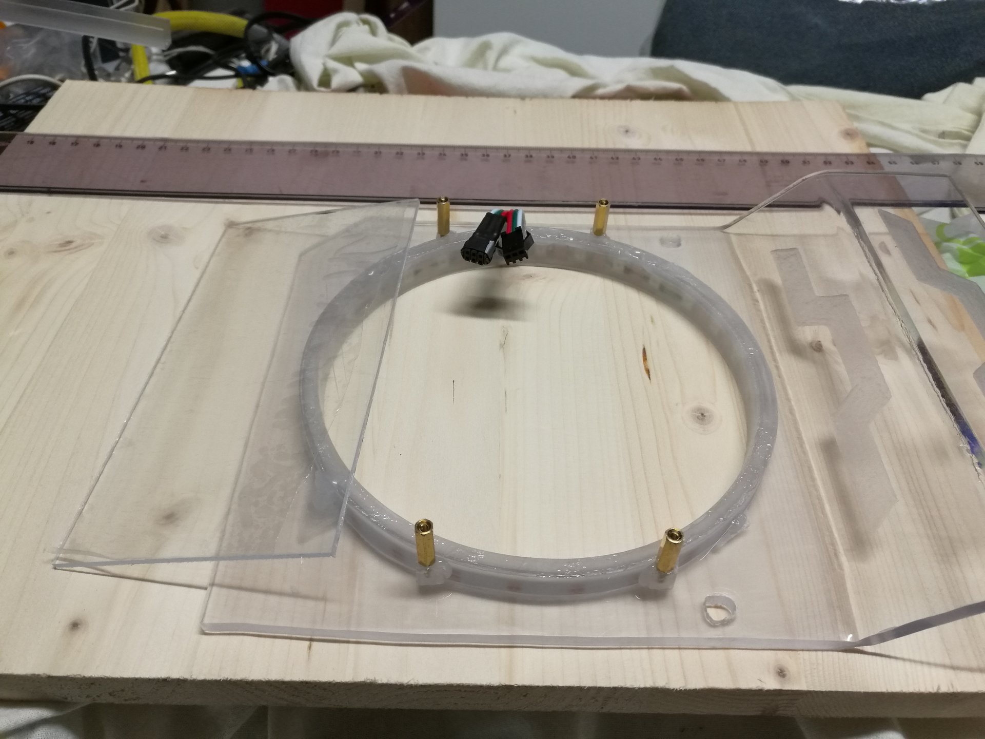
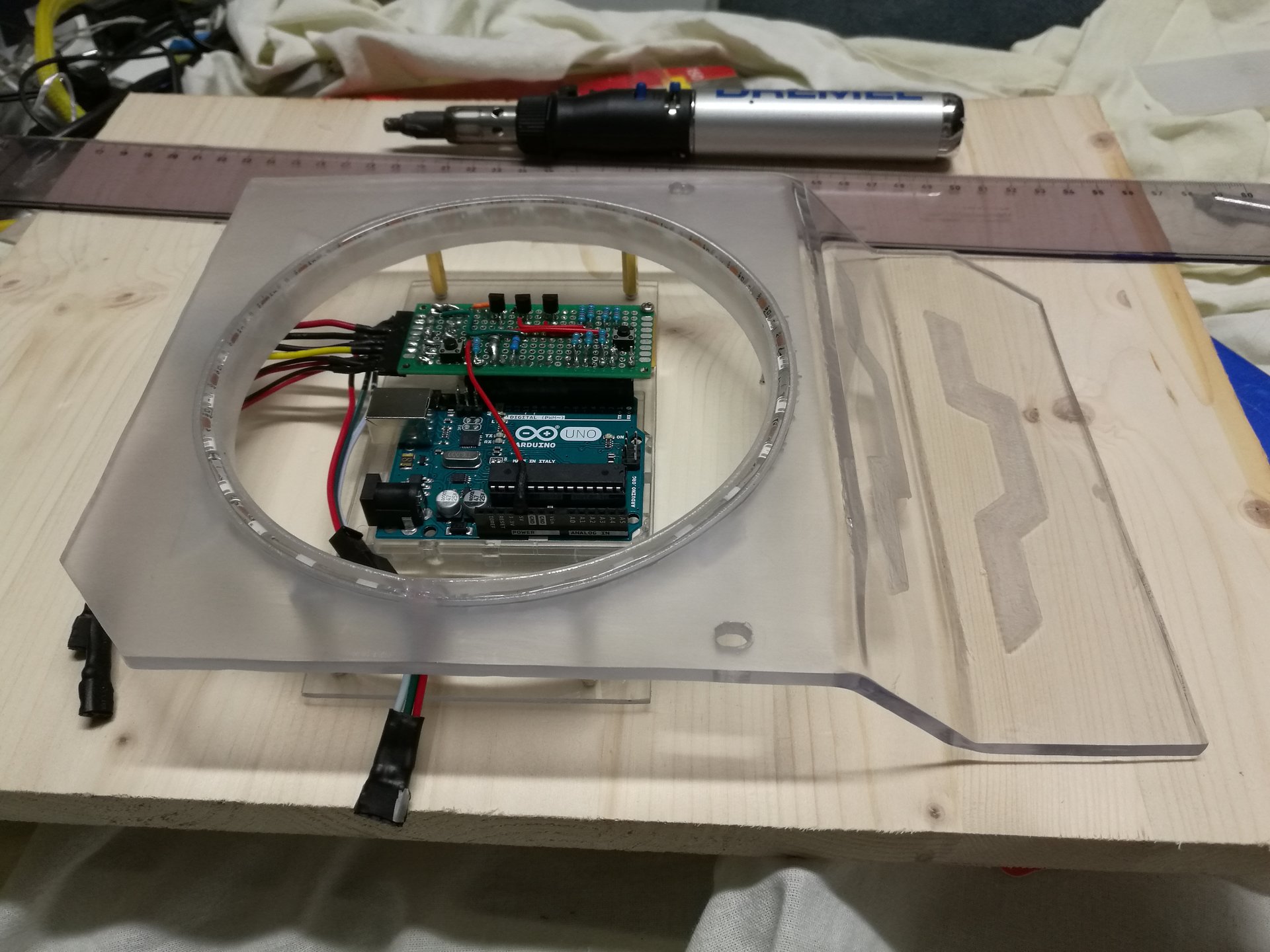
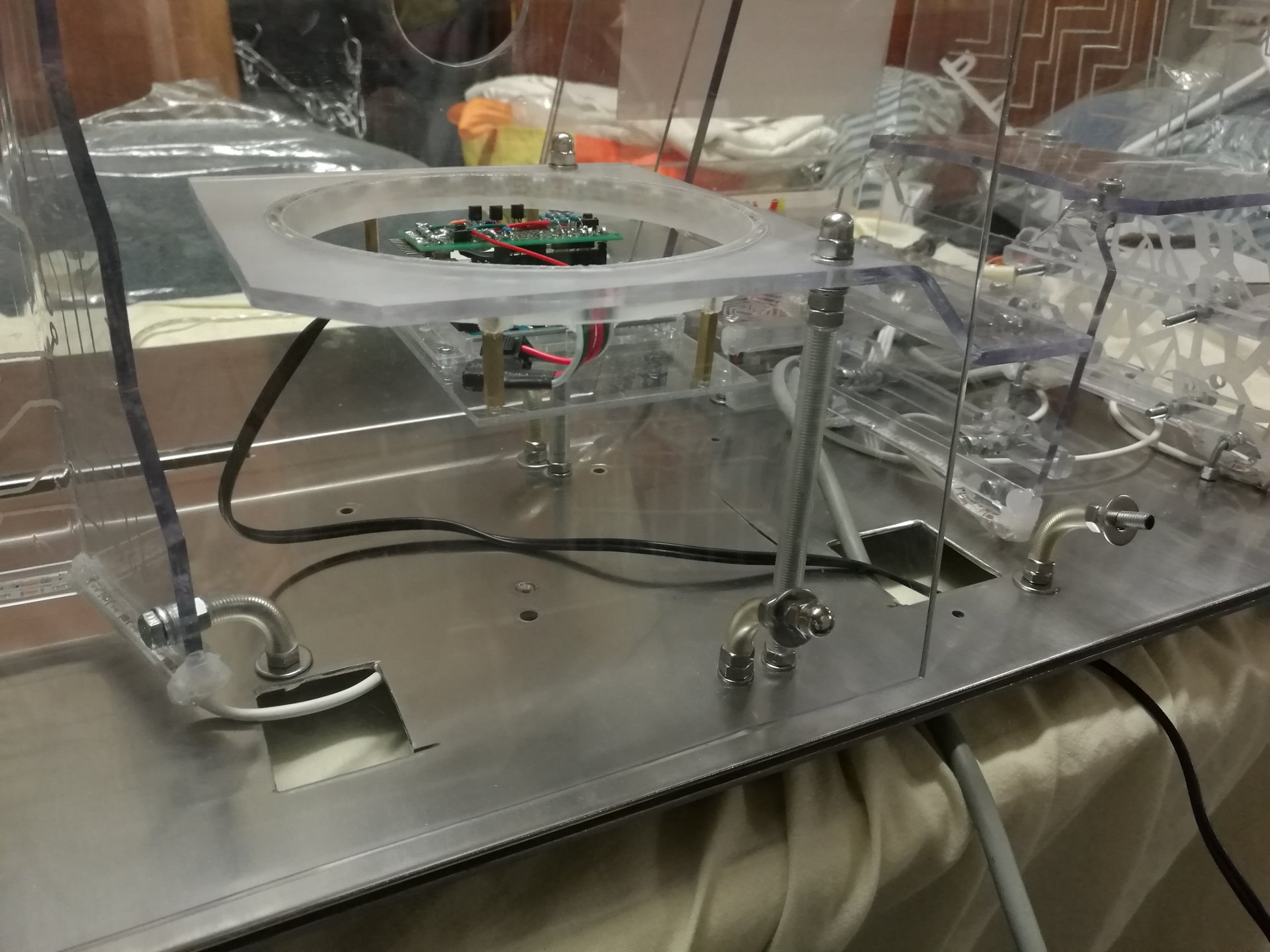
Here I cut the round hole:
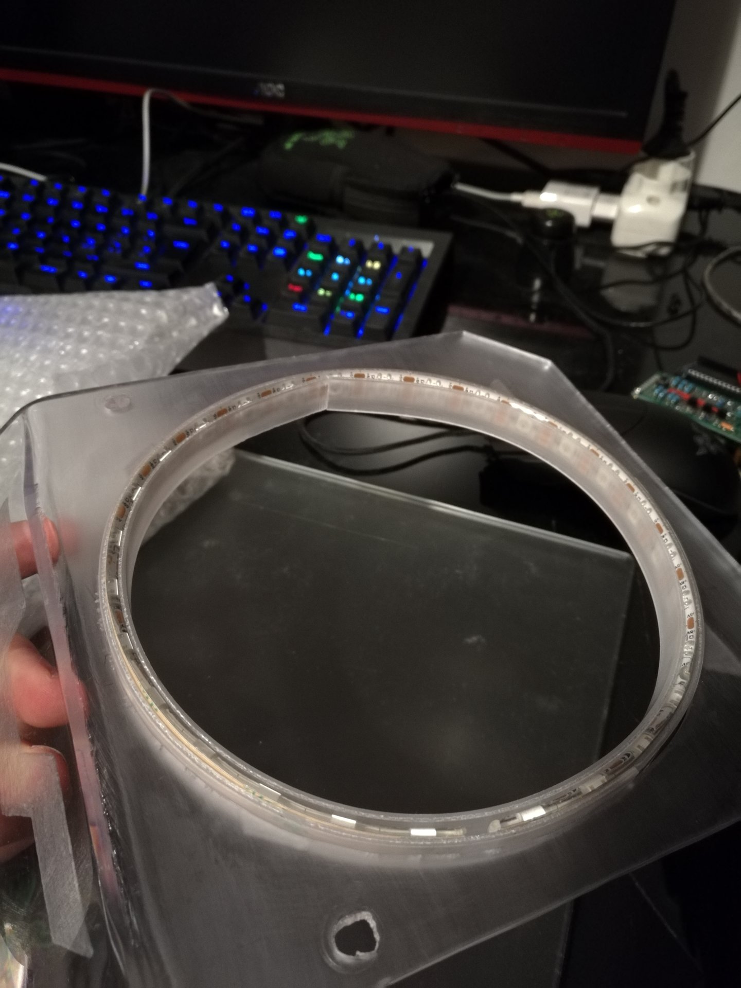
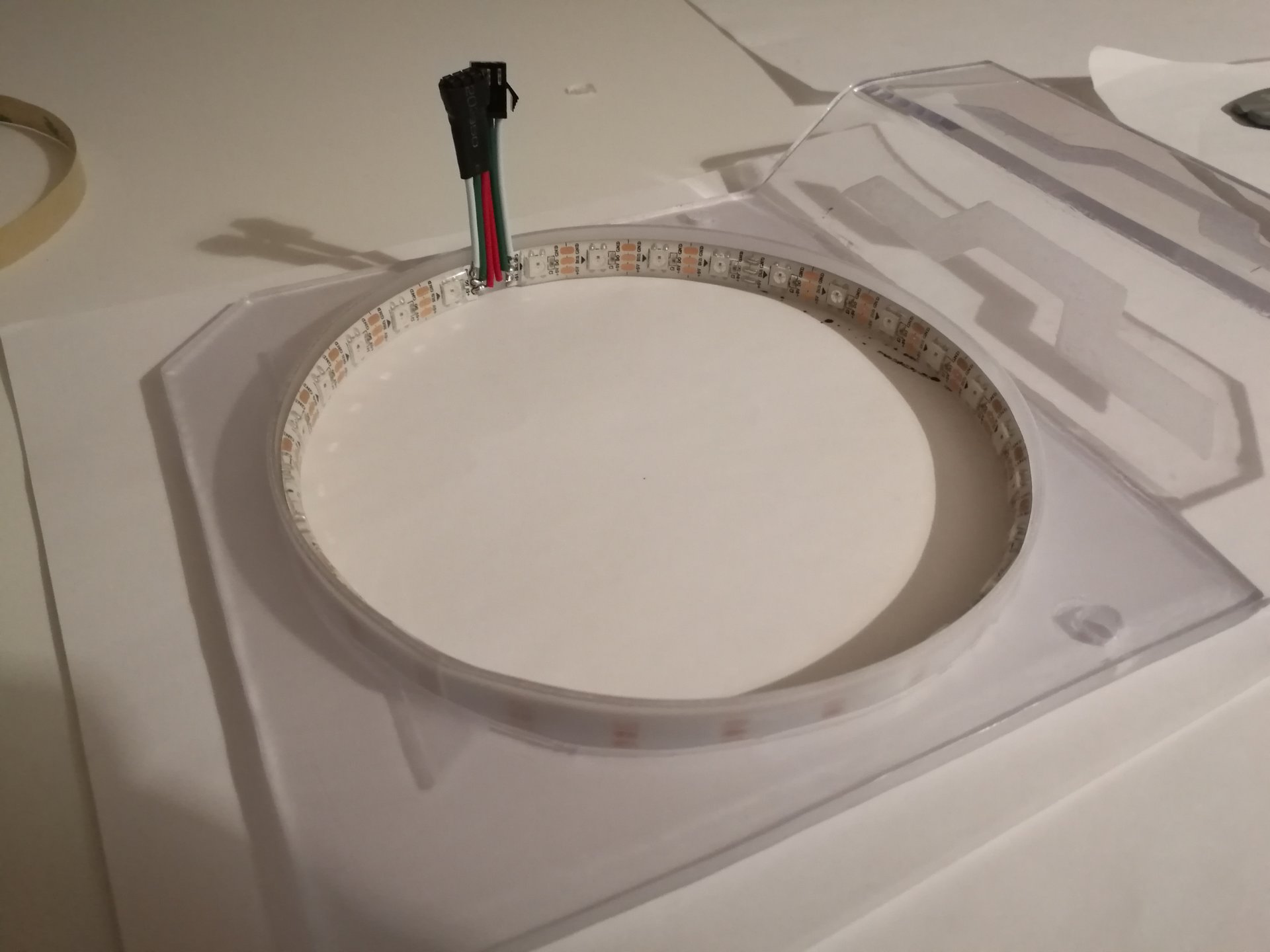
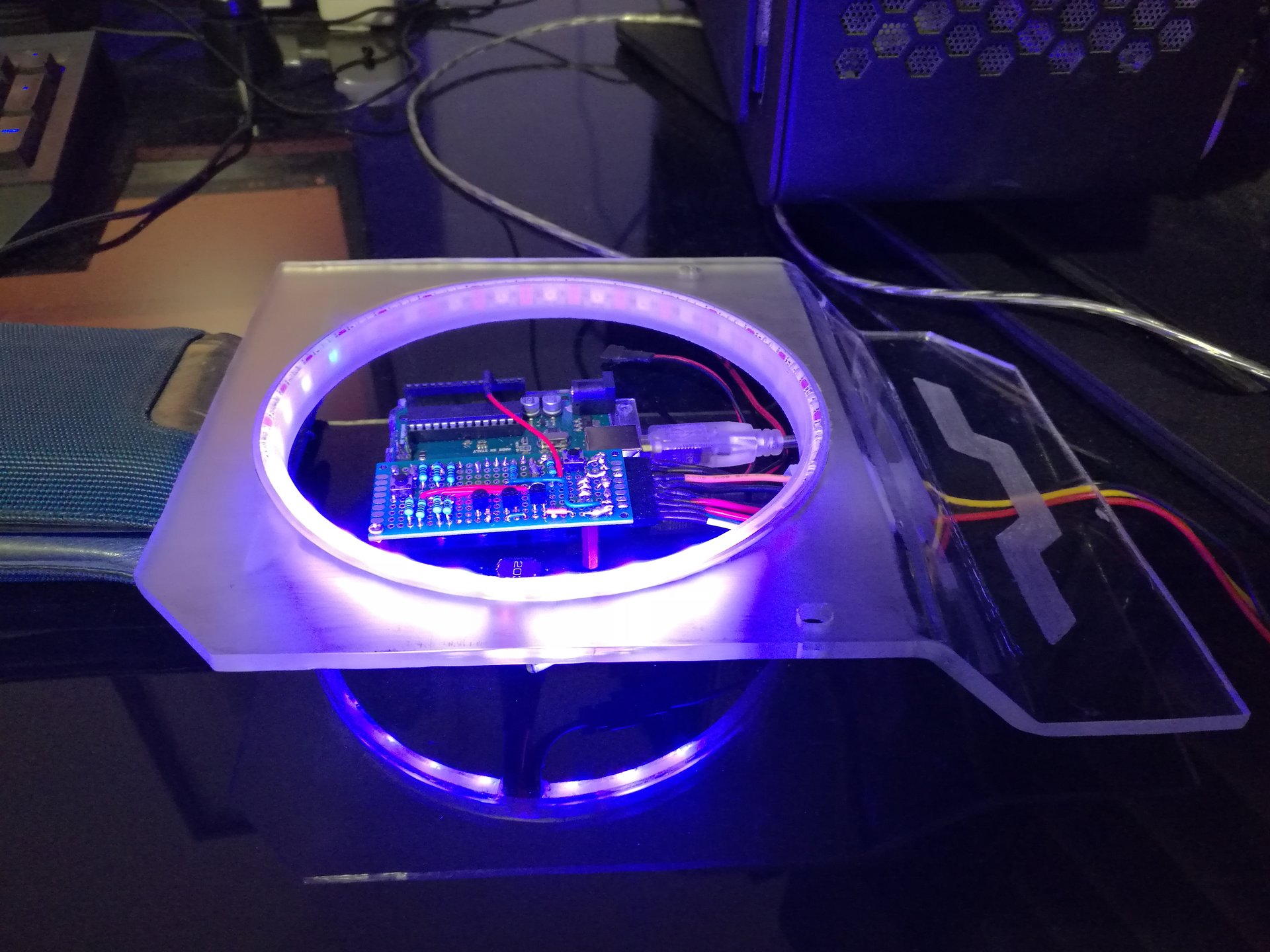
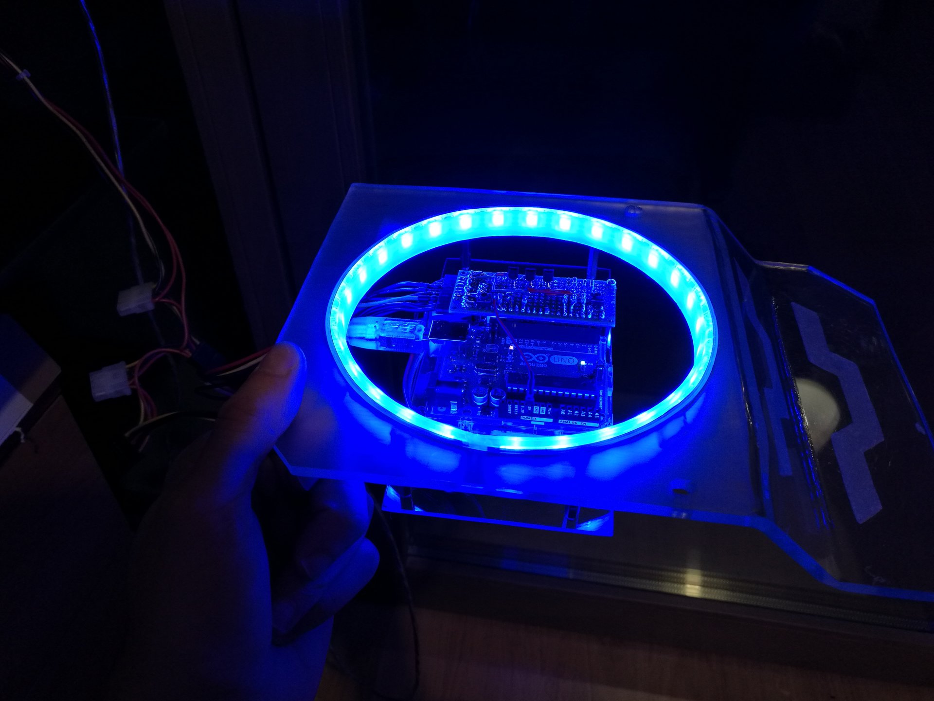
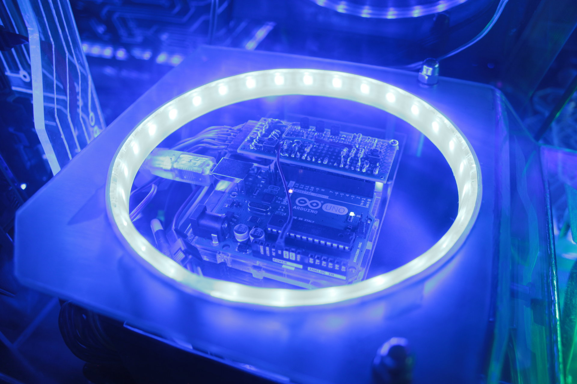
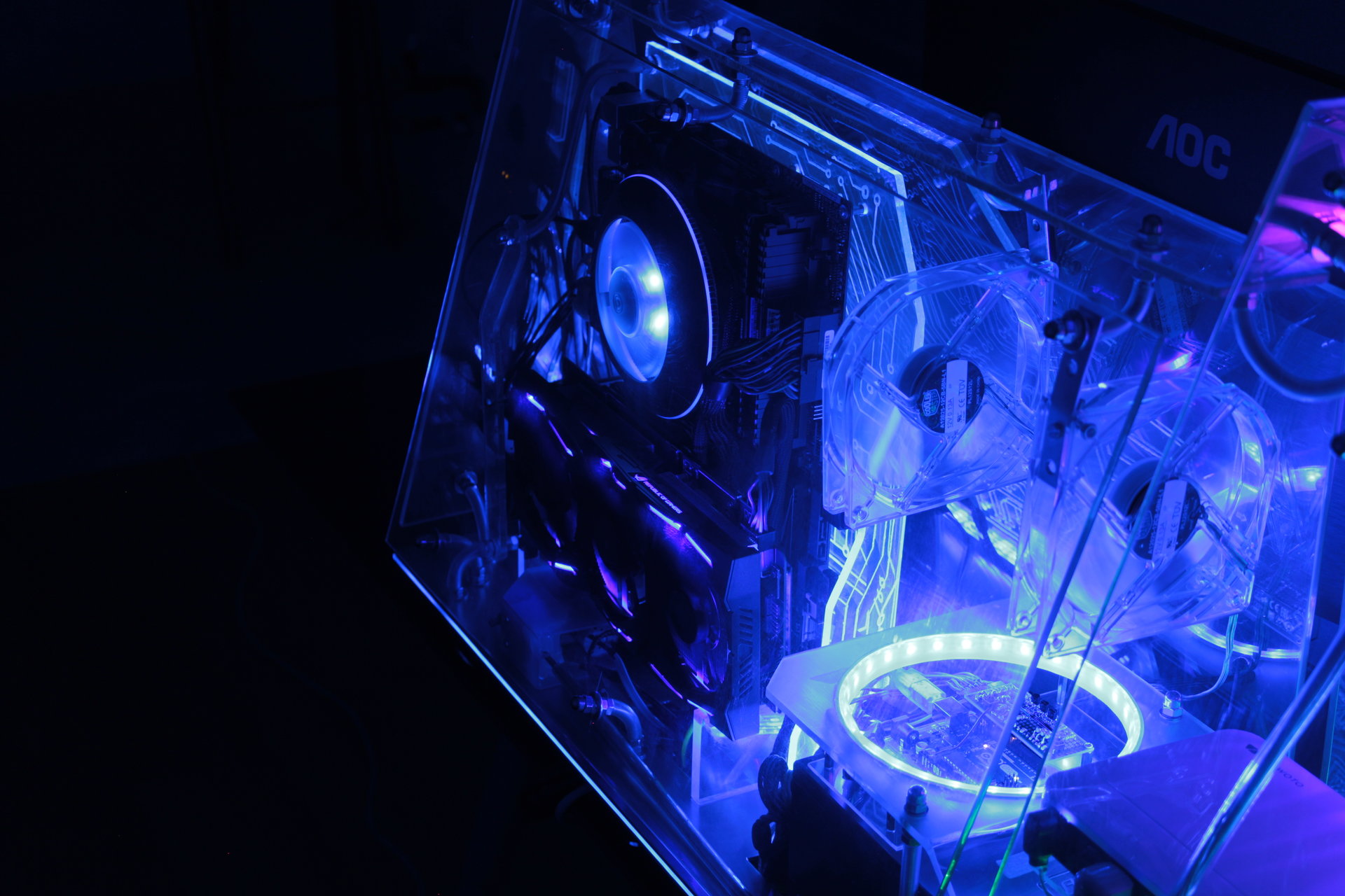
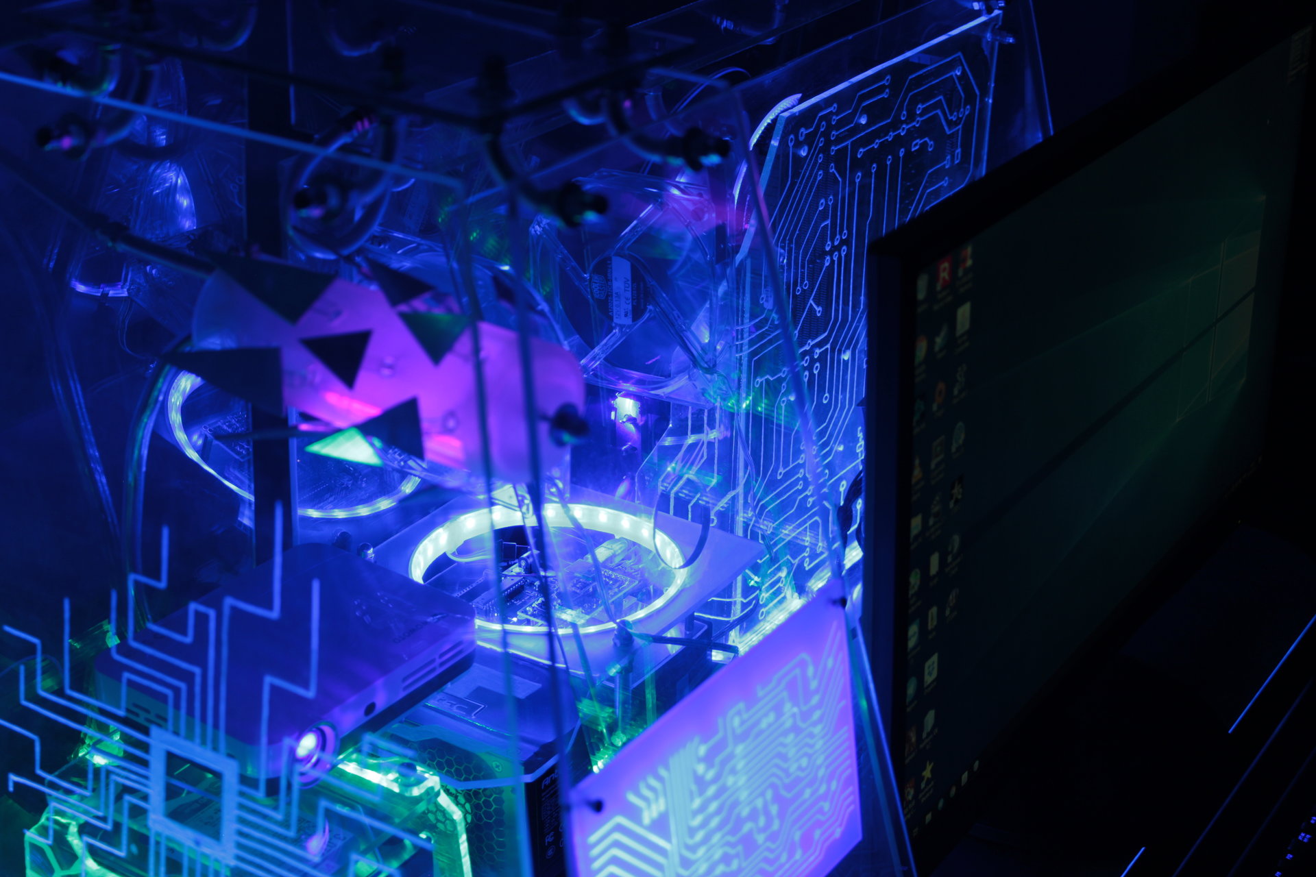
Then I have mounted the led strip on the hole edge! I used 3 layers to make this “light ring”: the first is a sanded polycarbonate strip fixed in the inner edge of the hole, the second is the actual led strip, and the third is another sanded polycarbonate strip, that covers the leds and spreads the light. It is a rounded led strip sandwich 😀
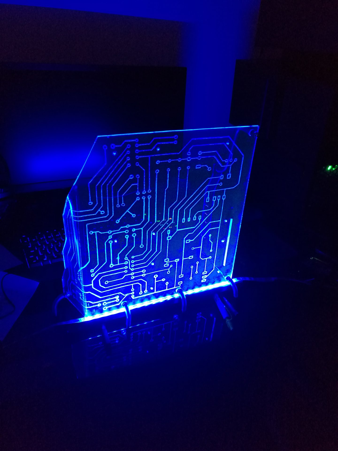
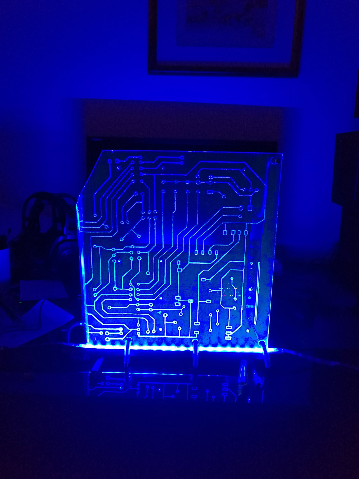
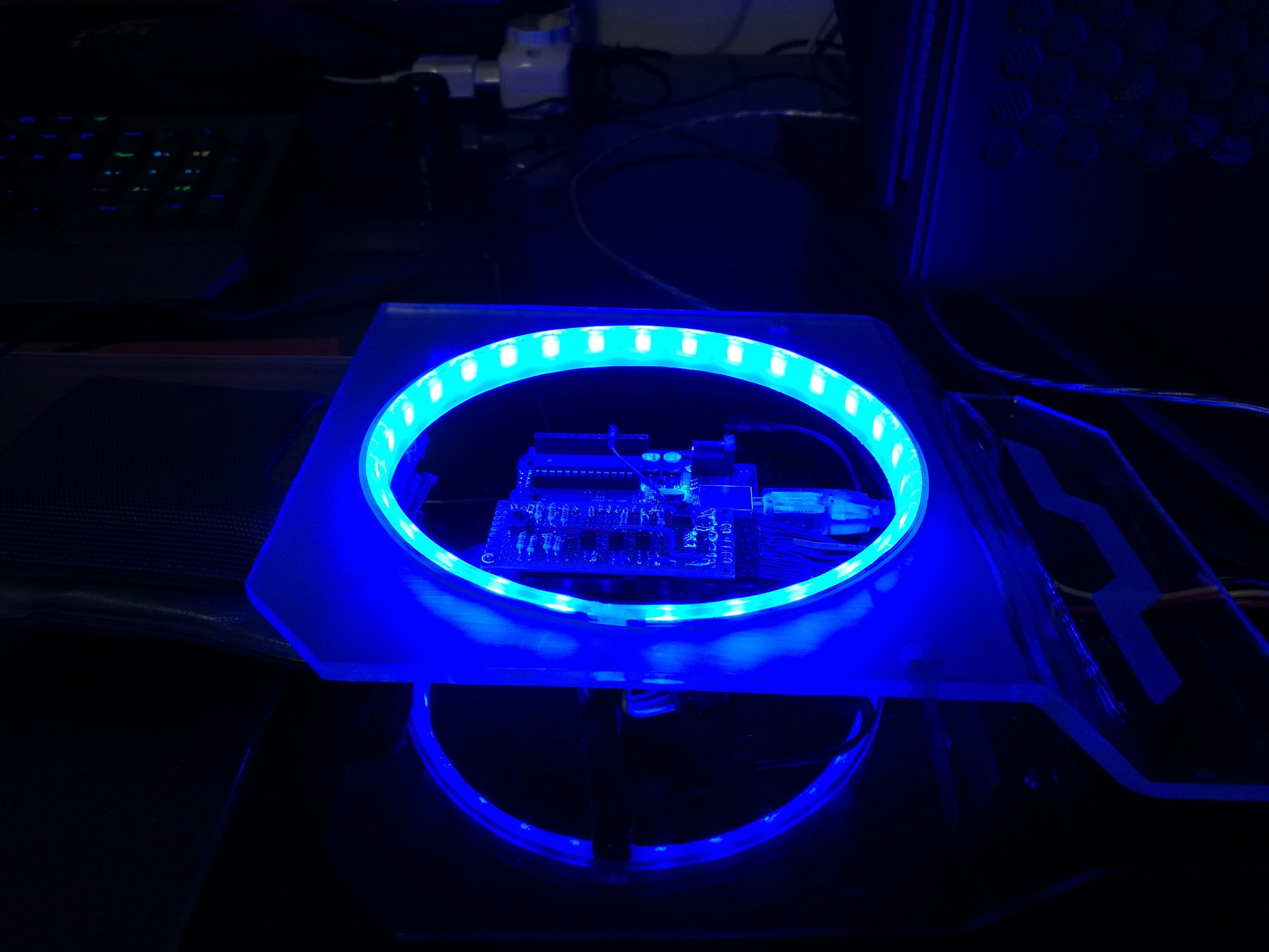
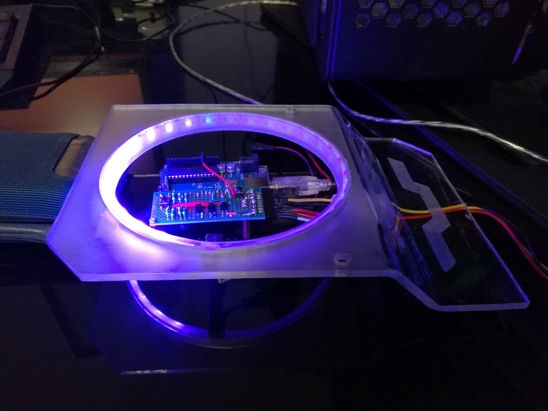
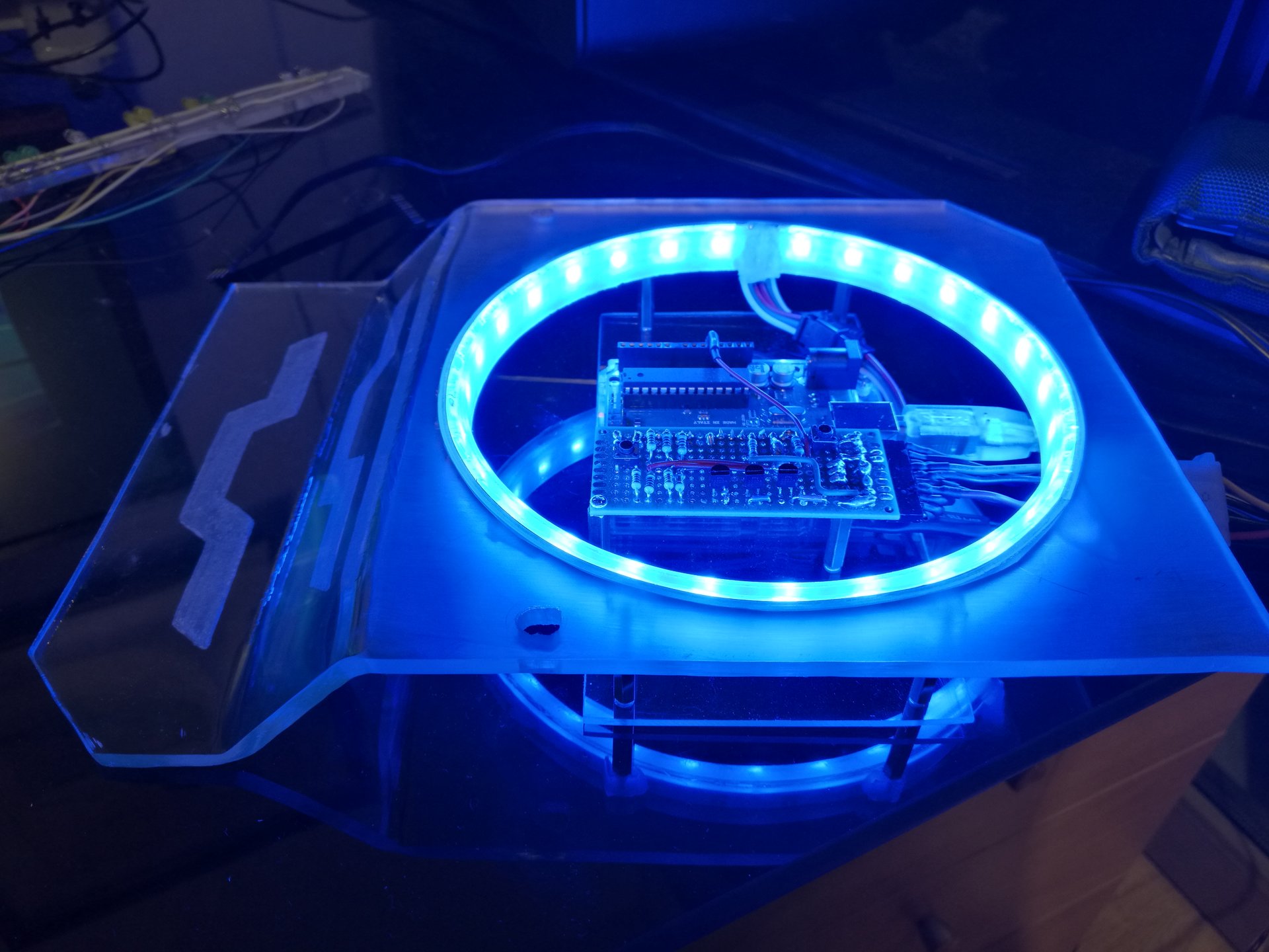
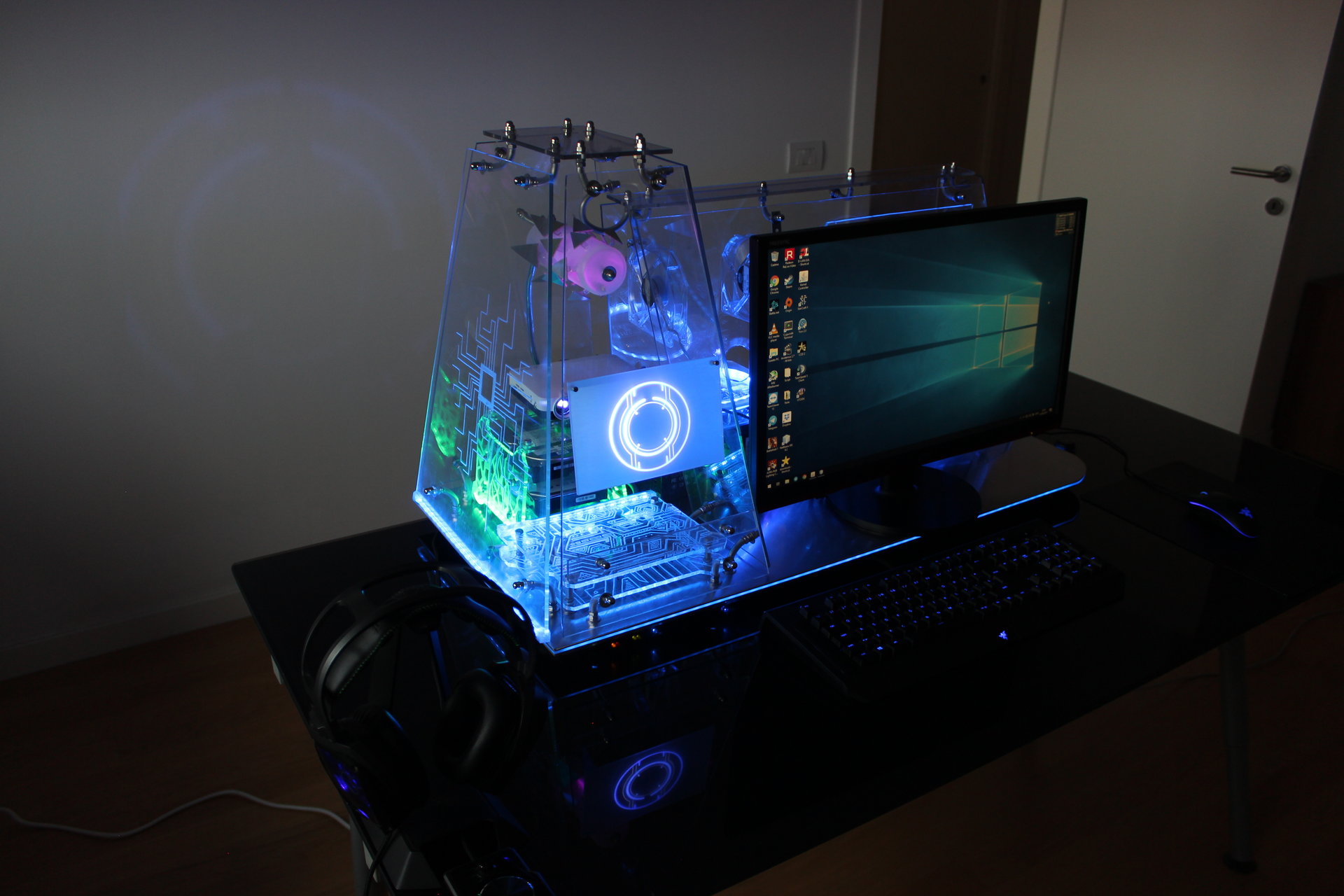
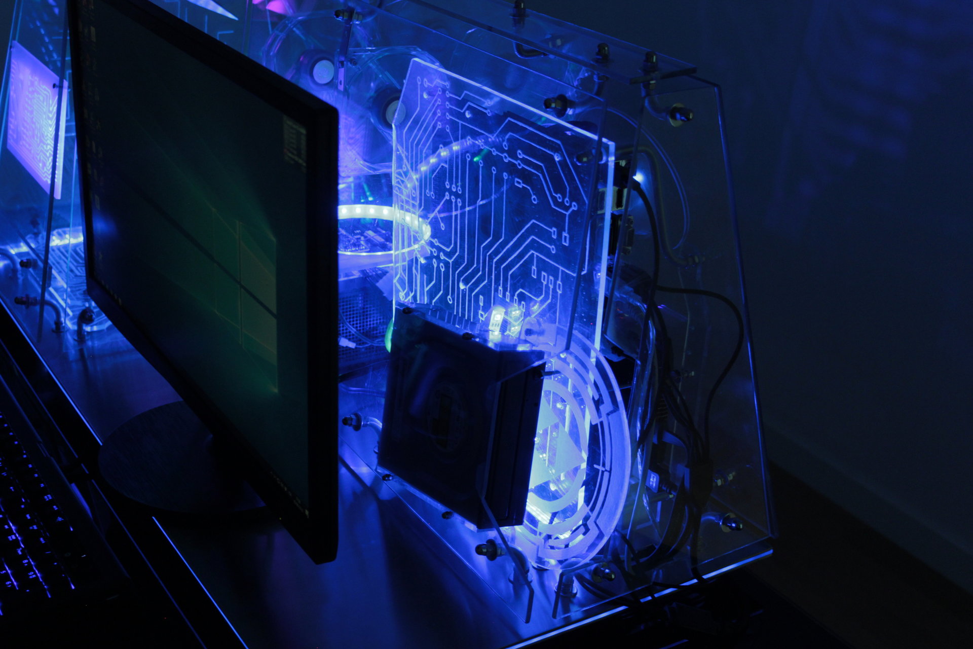
This is the lighted result:
and some videos of an animated effect that I programmed, a “pixel with trail” that runs in circle 😀 :
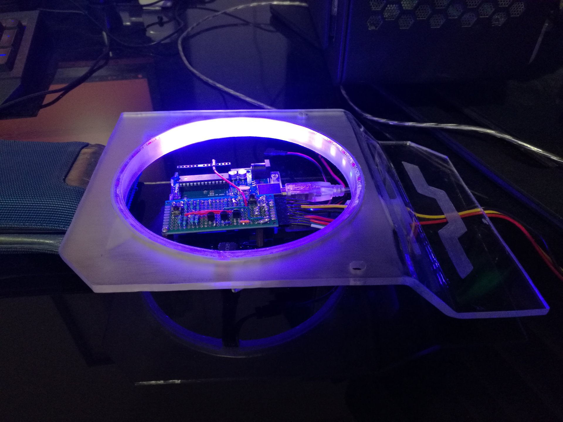
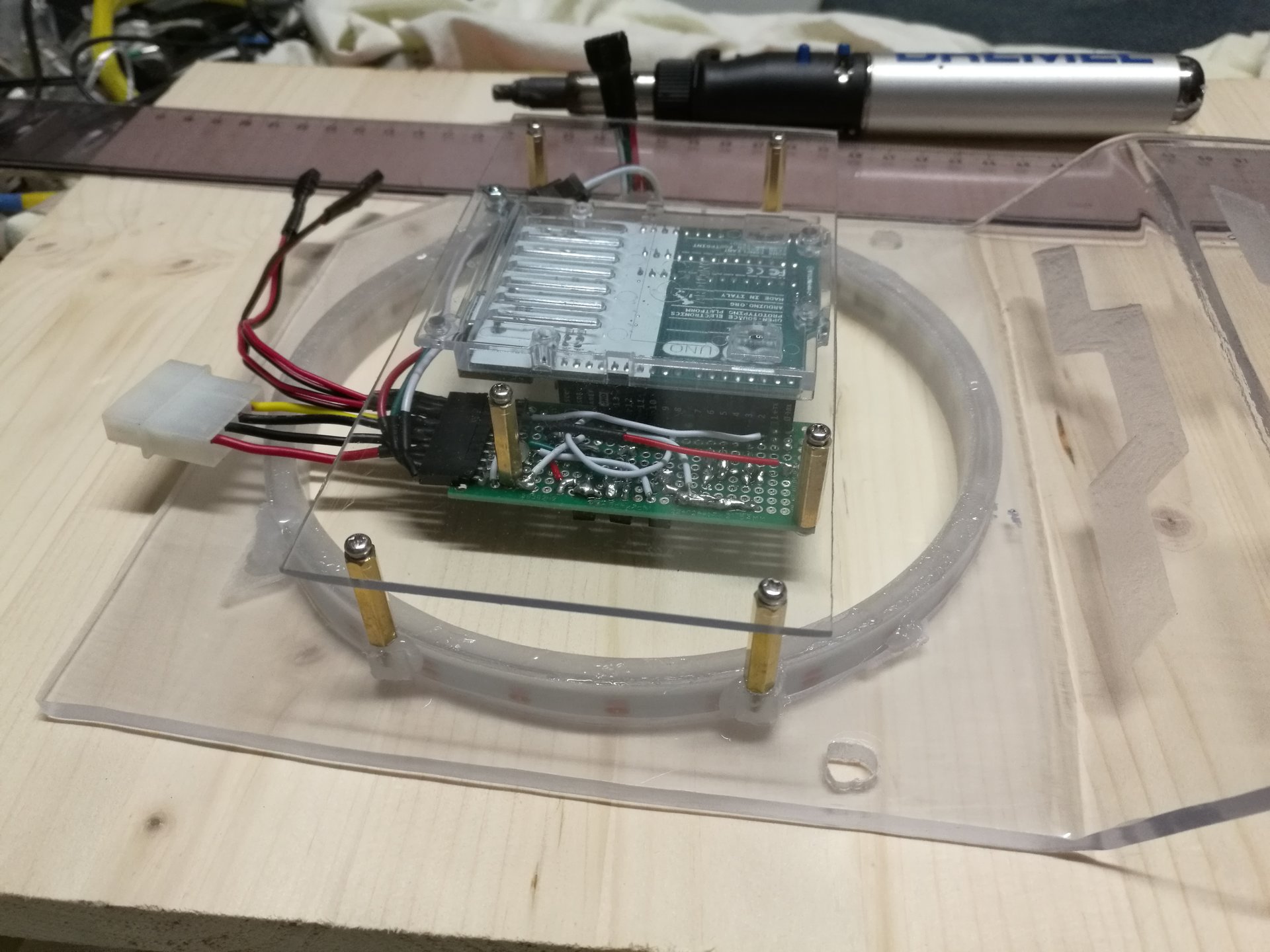
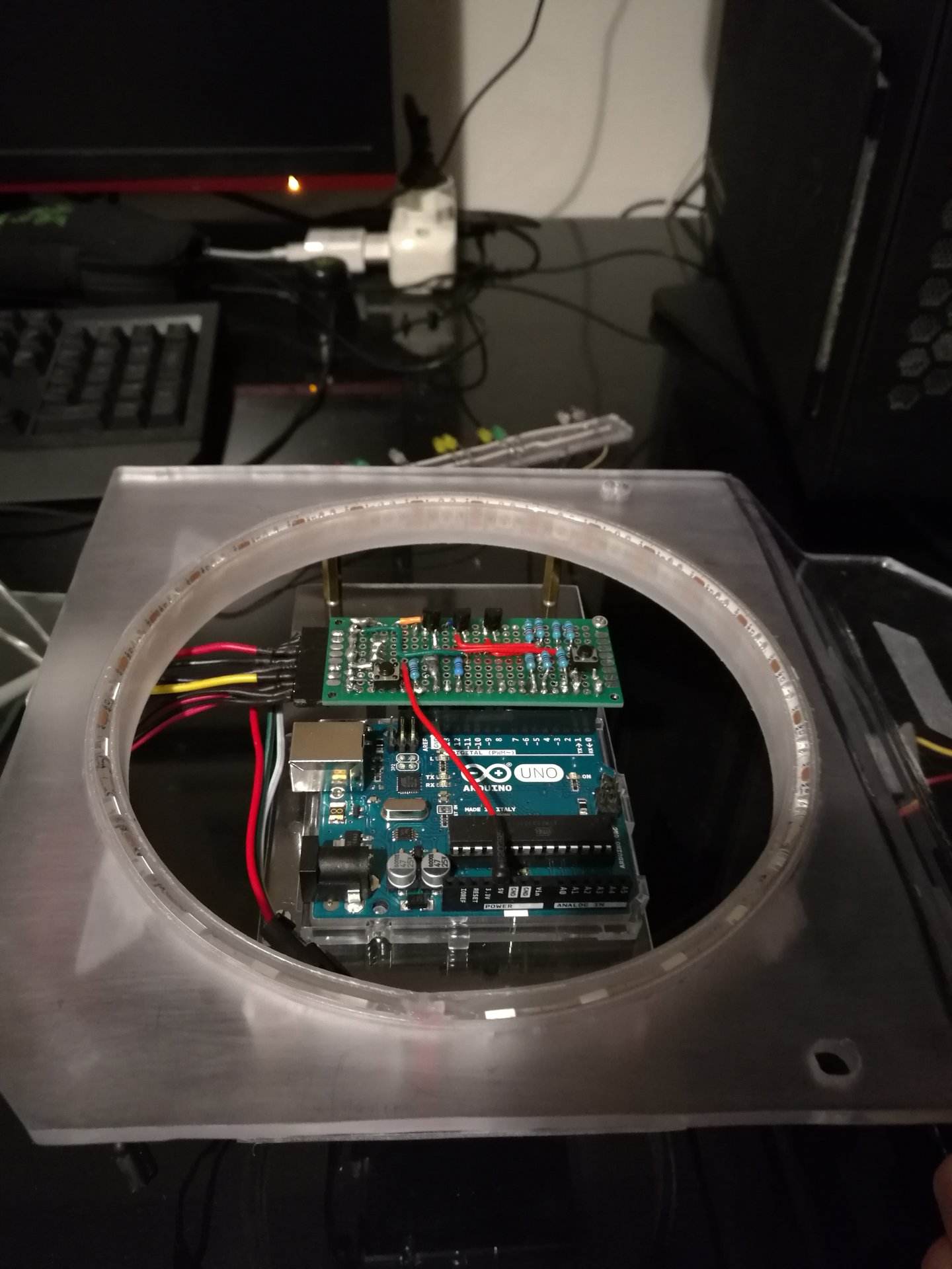
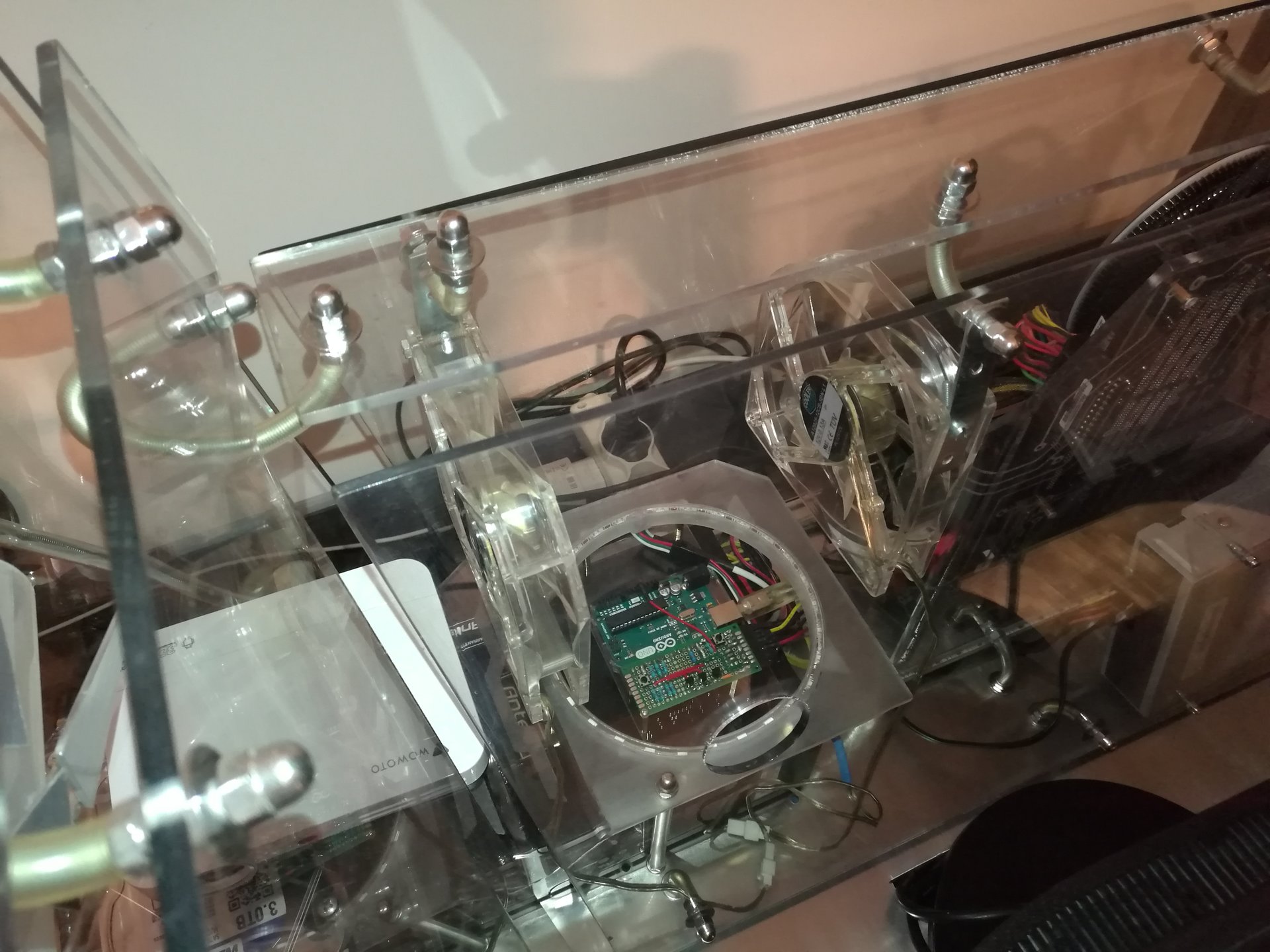
Then I have made a transparent support to mount Arduino inside the ring:
And finally another video of the animated effect, with Arduino mounted inside:
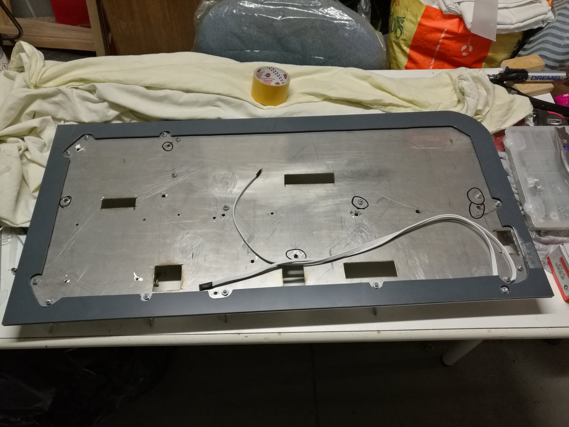
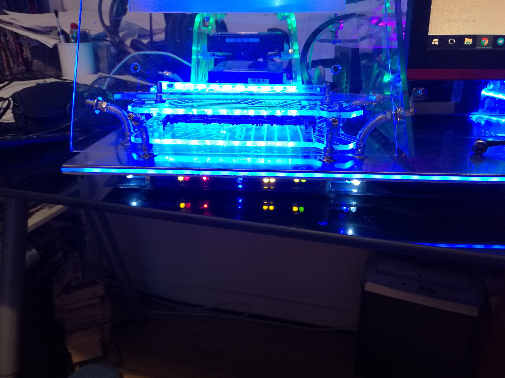
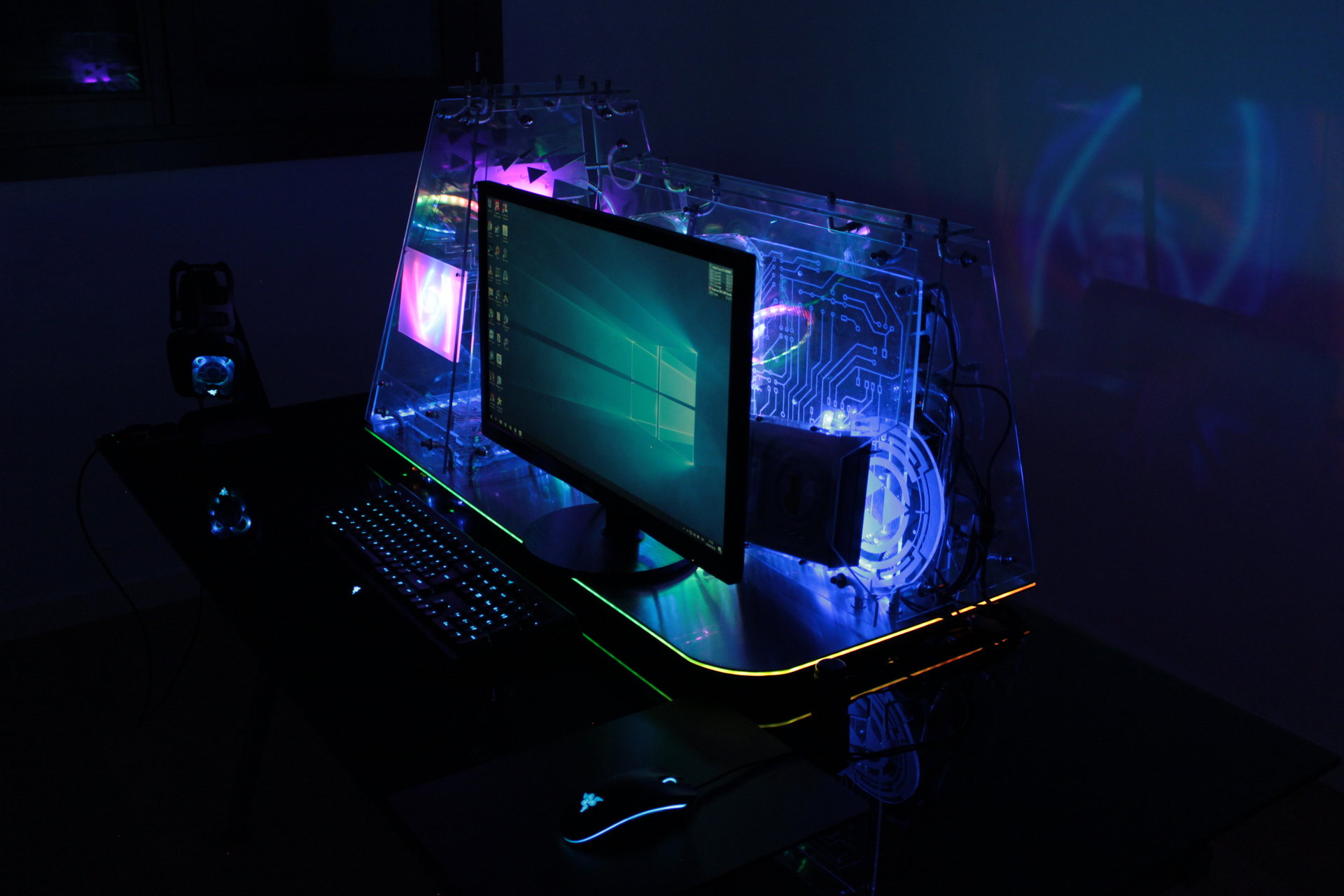
I have added another thing to the case: a lighted border for the steel base!
I had done this kind of work before on another mod (this modded Level 10: ), and the first time was a long sequence of failed attemps, but now I already know how to do it in the correct way (the right materials, proportions, methods, etc.), so this second time has been a lot easier.
Basically the idea is to make a “sandwich” with a translucent layer lighted from inside, between two opaque layers (one of them is the steel base).
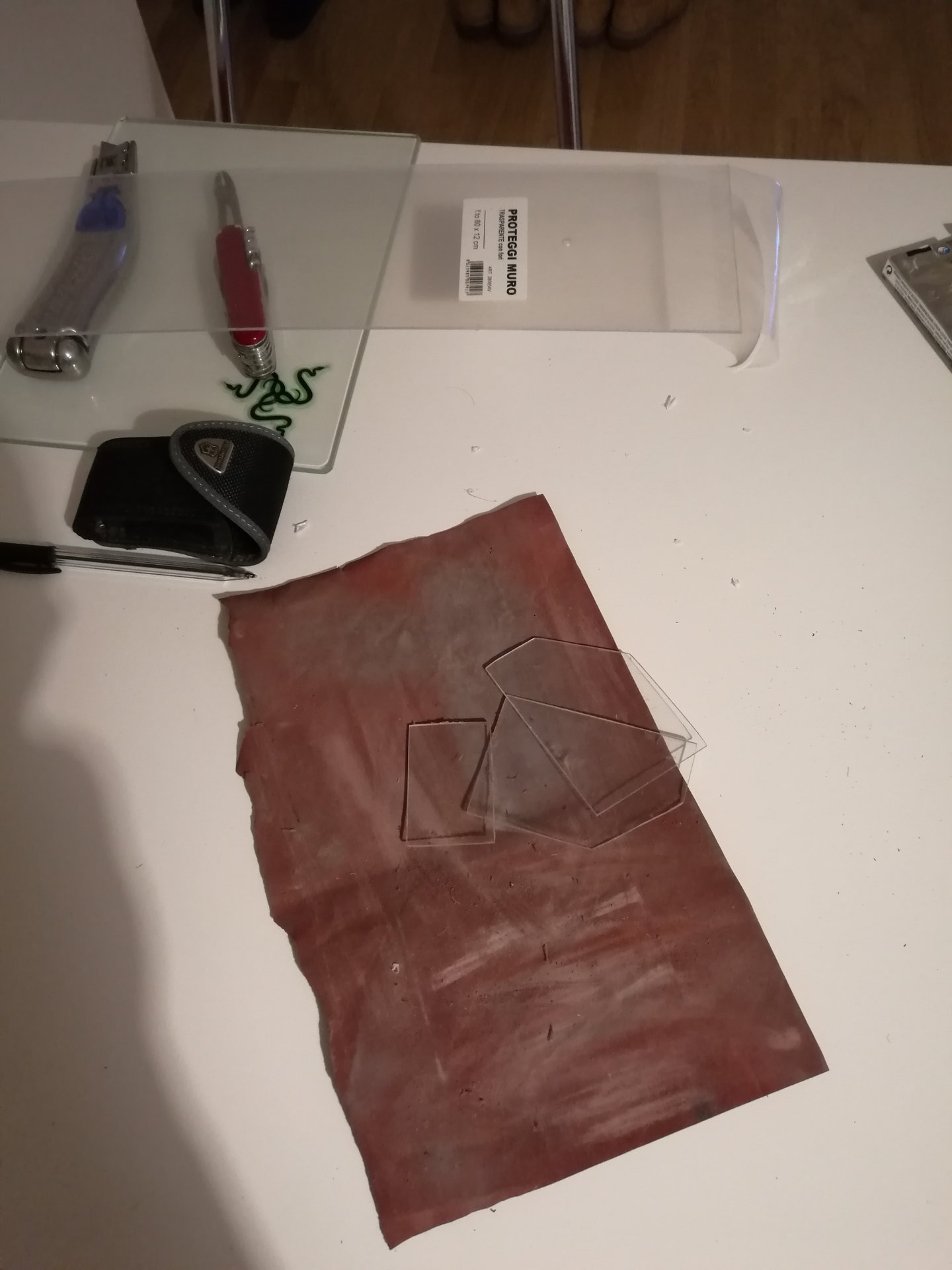
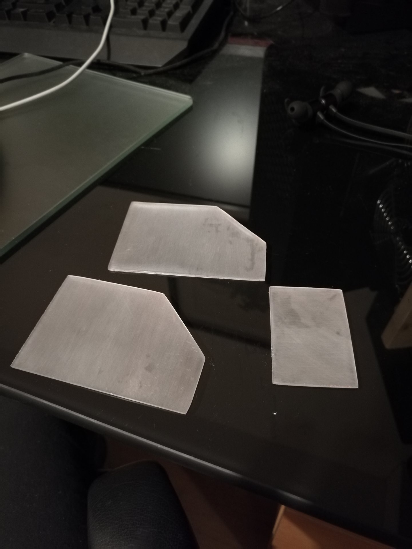
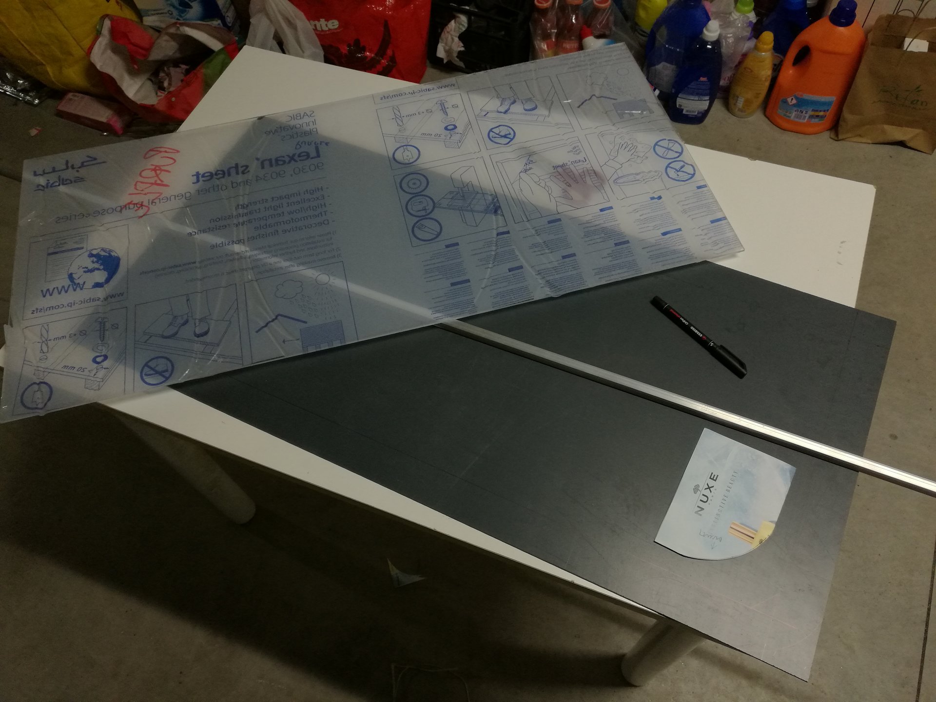
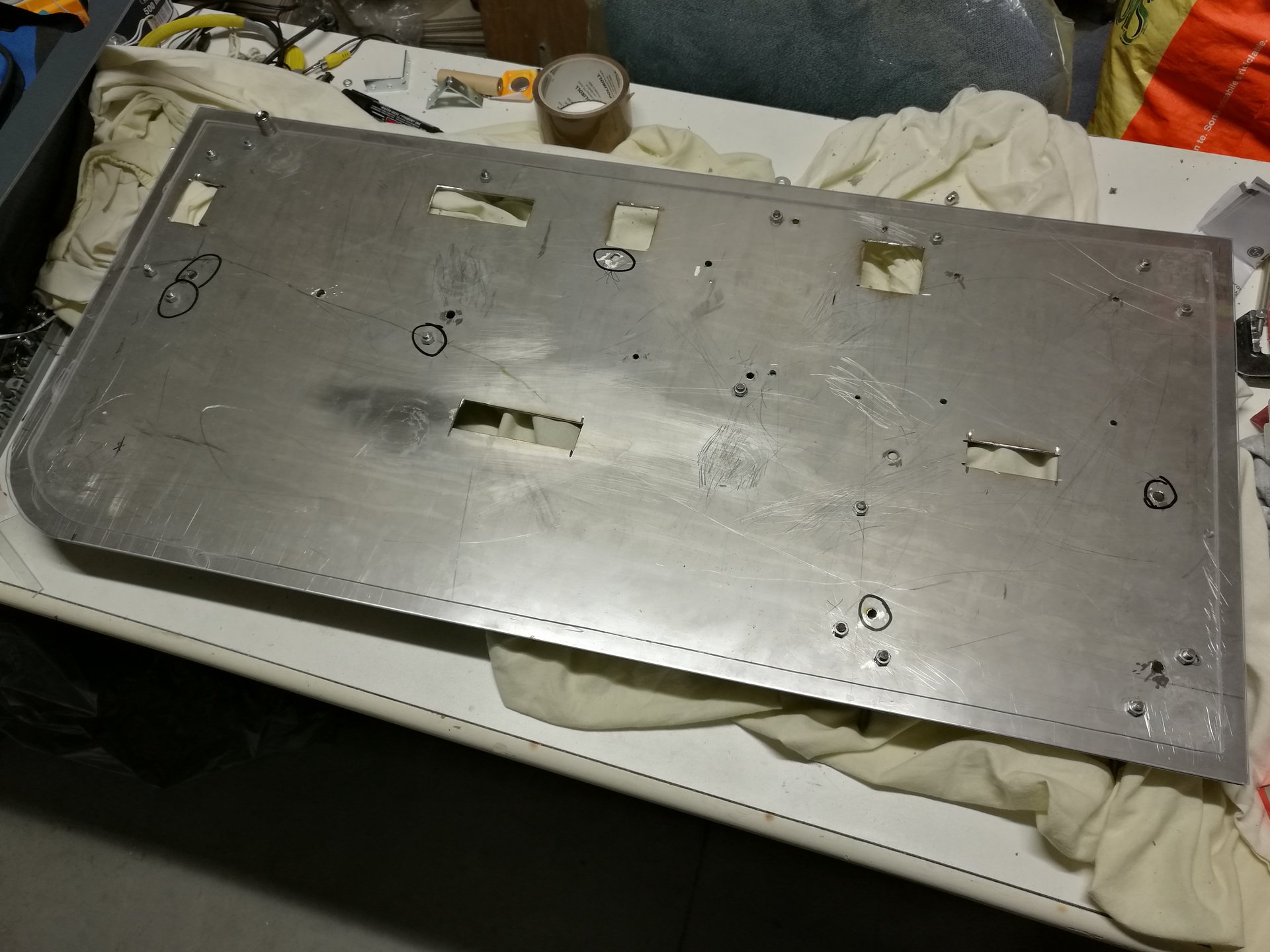
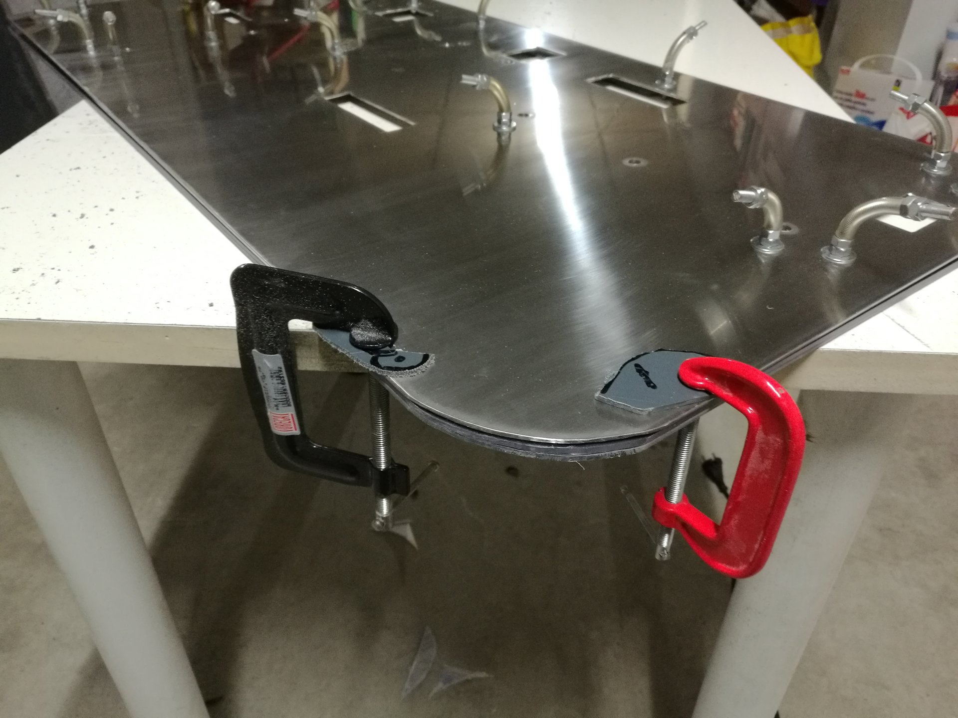
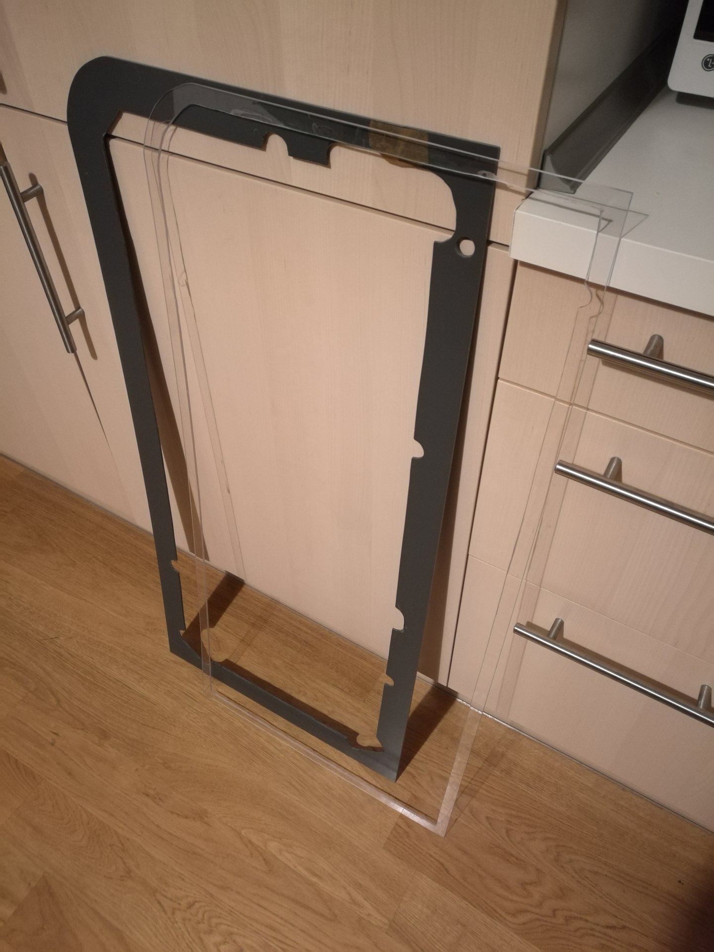
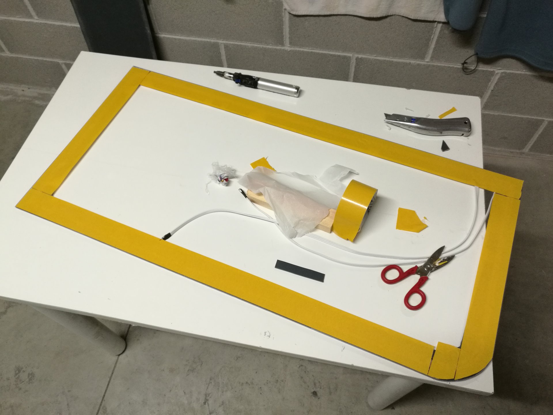
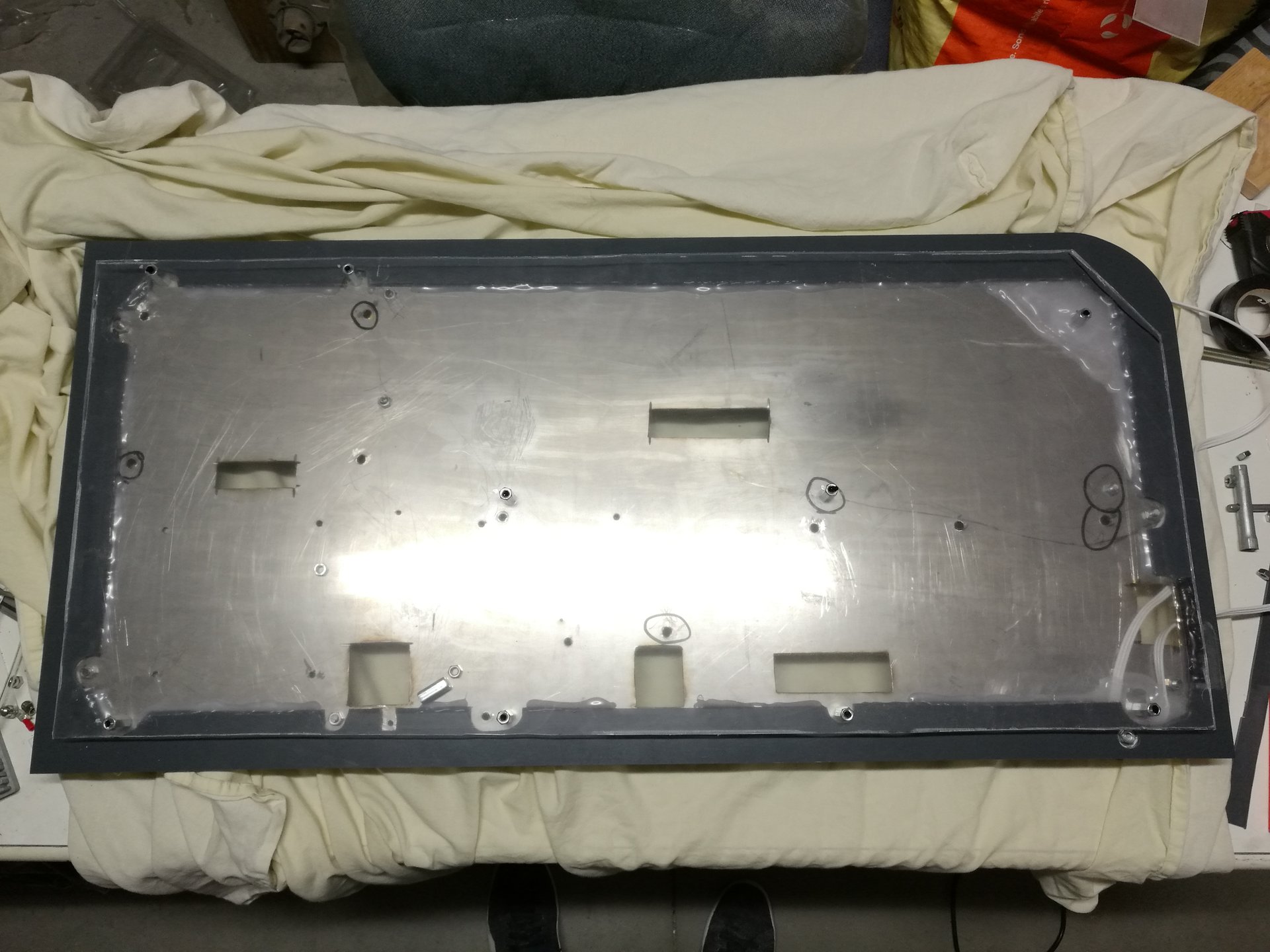
First I cut two frames from two panels of the same size of the base, one in transparent polycarbonate and one in opaque grey PVC:
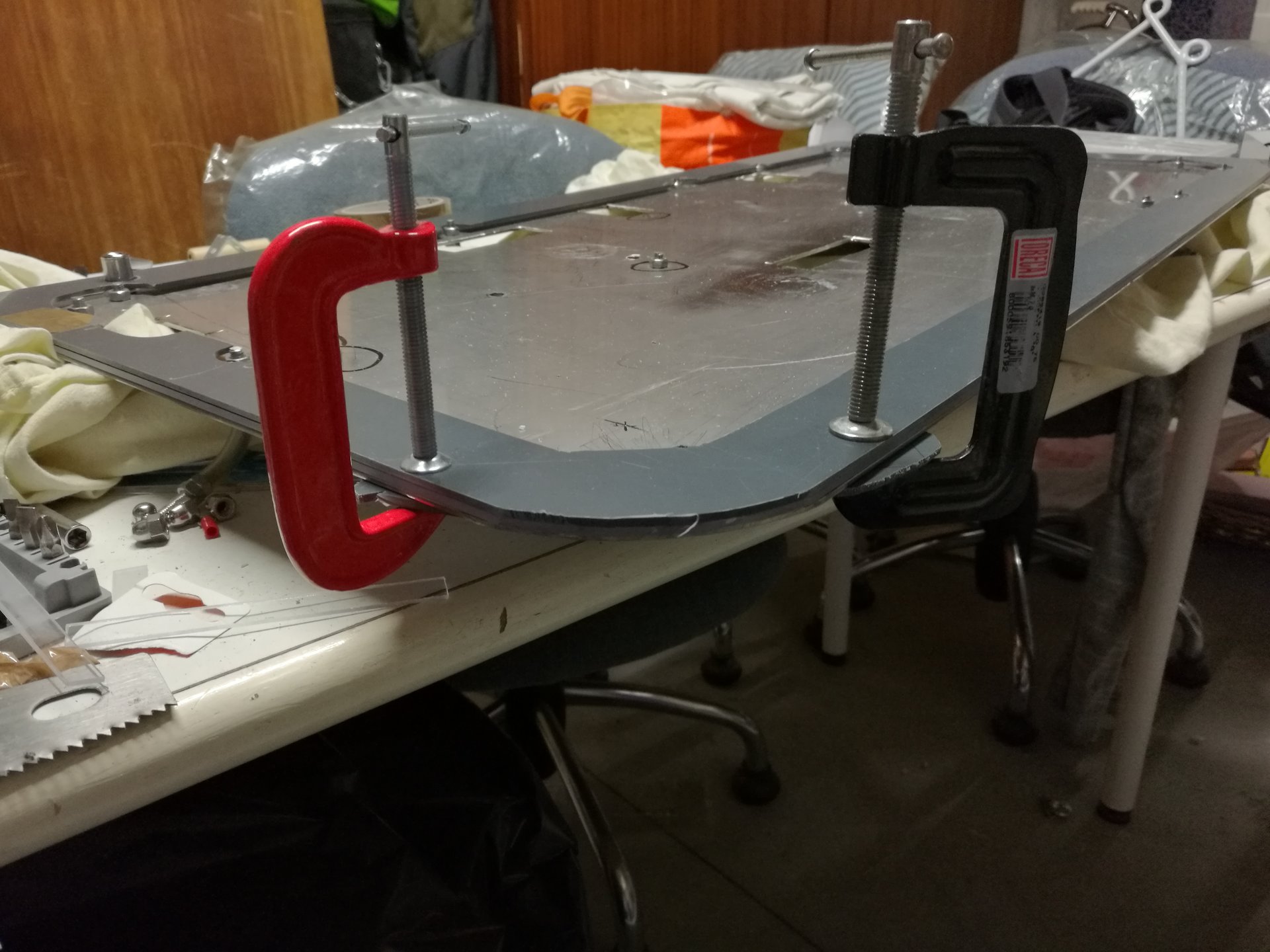
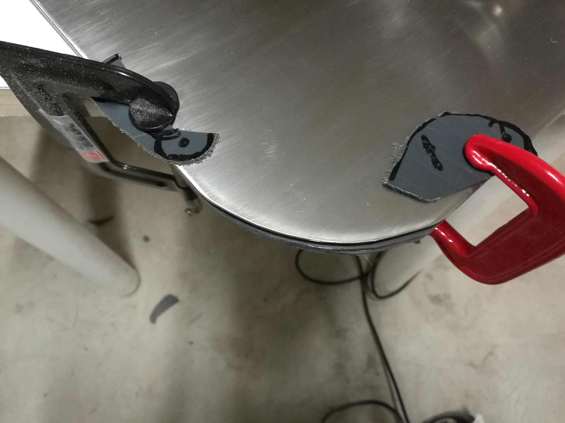
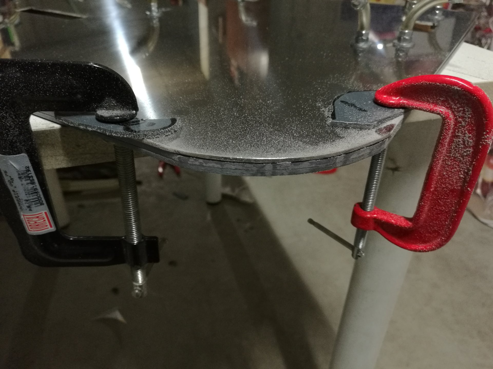
Then I have fixed the frames and the base together, to profile their borders like the rounded corner of the base:
Then I have sanded the edges of both panels, and I have washed them to remove all the dust:
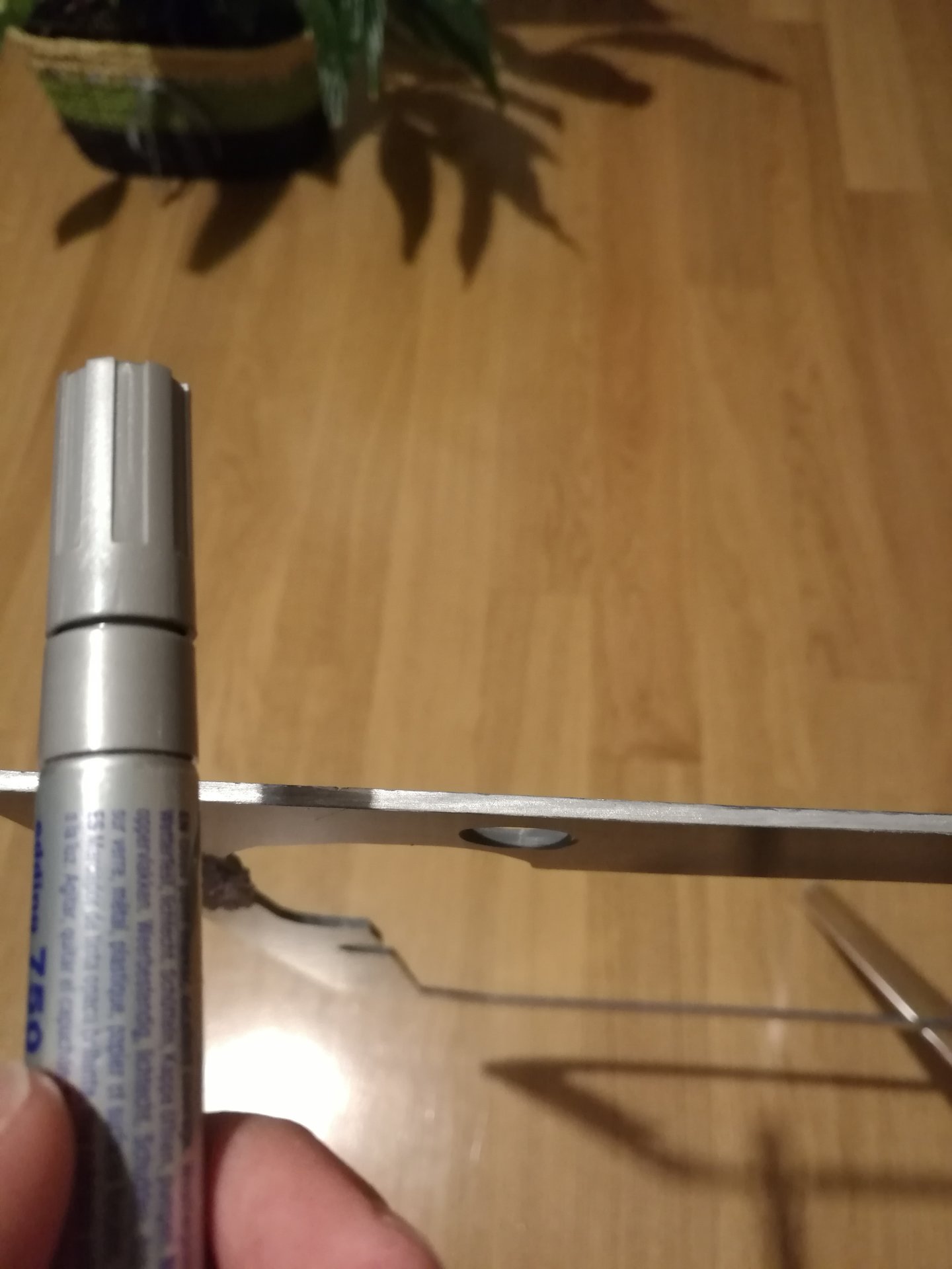
To make the right “sandwich”, the two external layers must seem equals, so I painted the border of PVC frame with a silver paint marker:
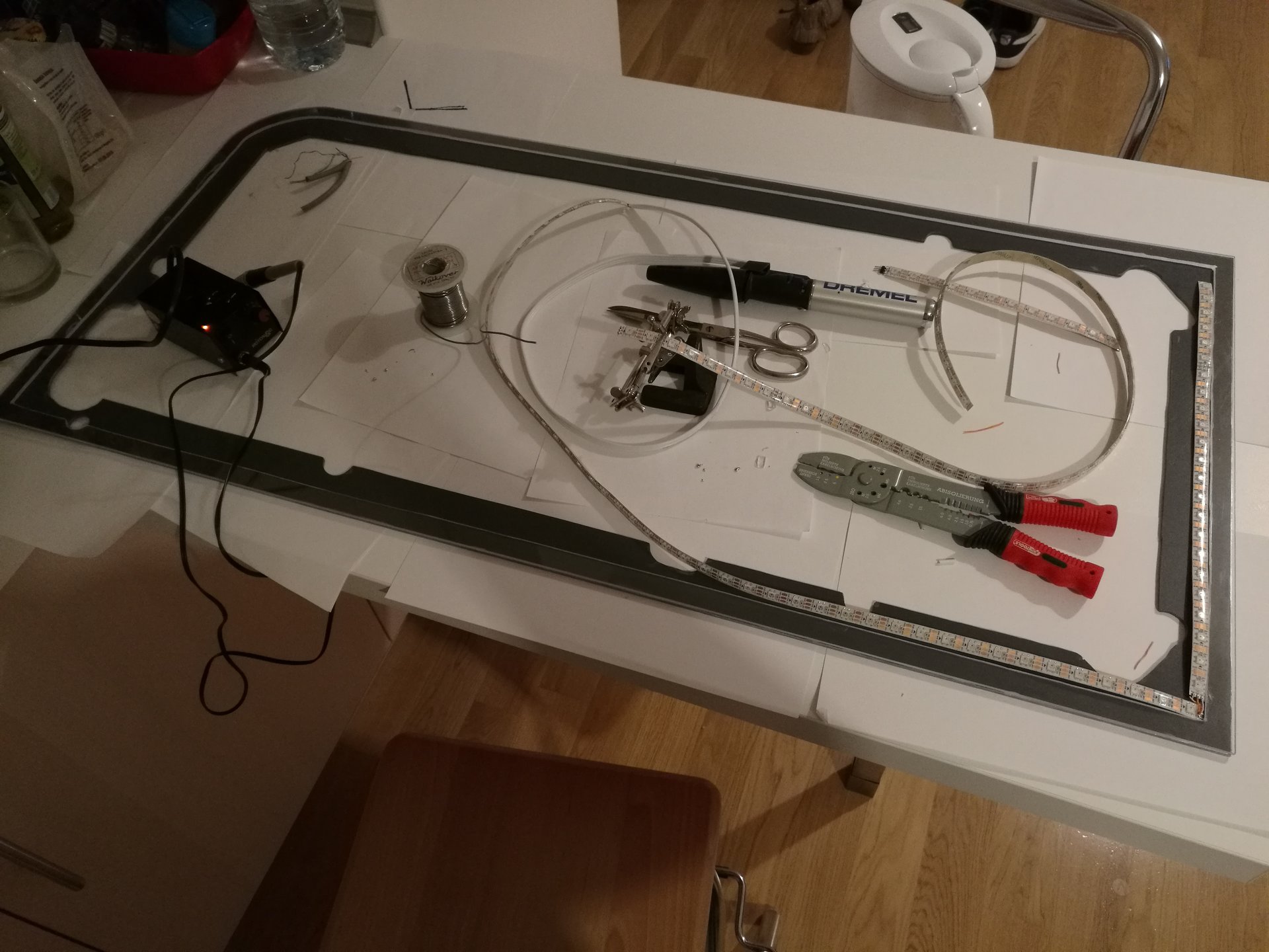
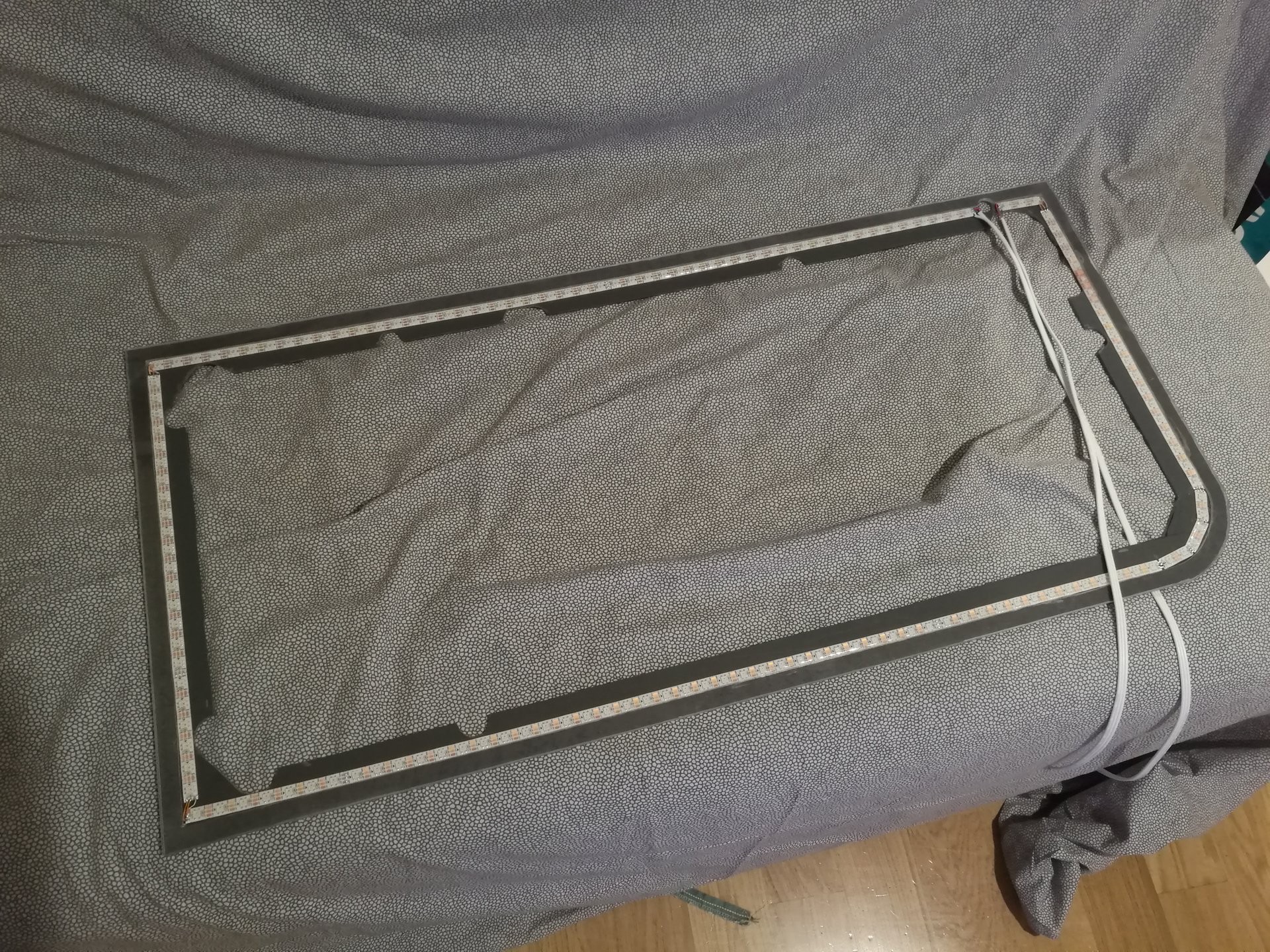
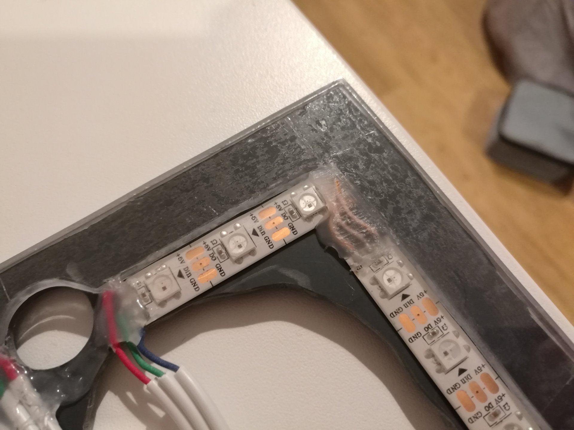
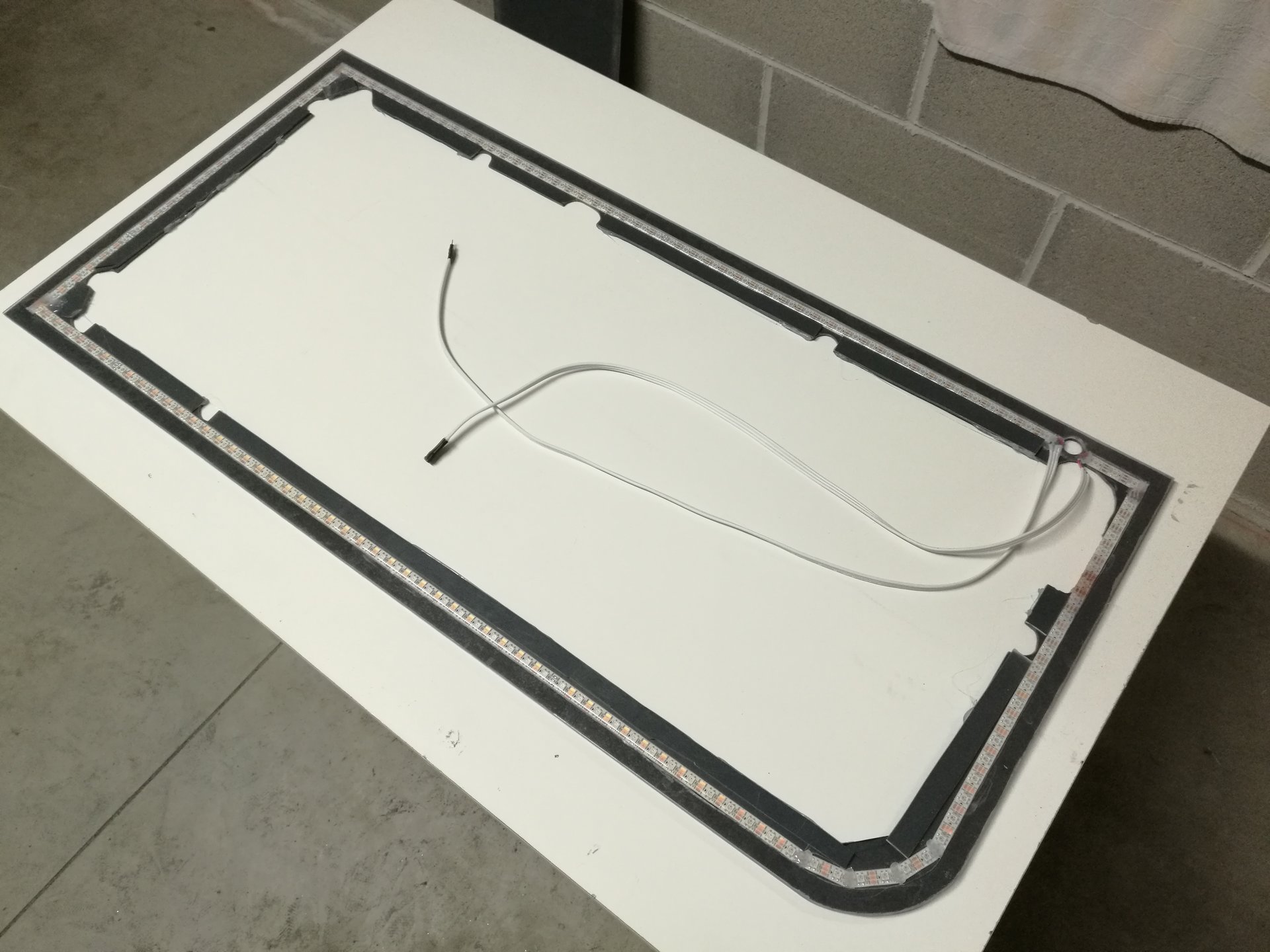
Then I soldered and glued the led strips:
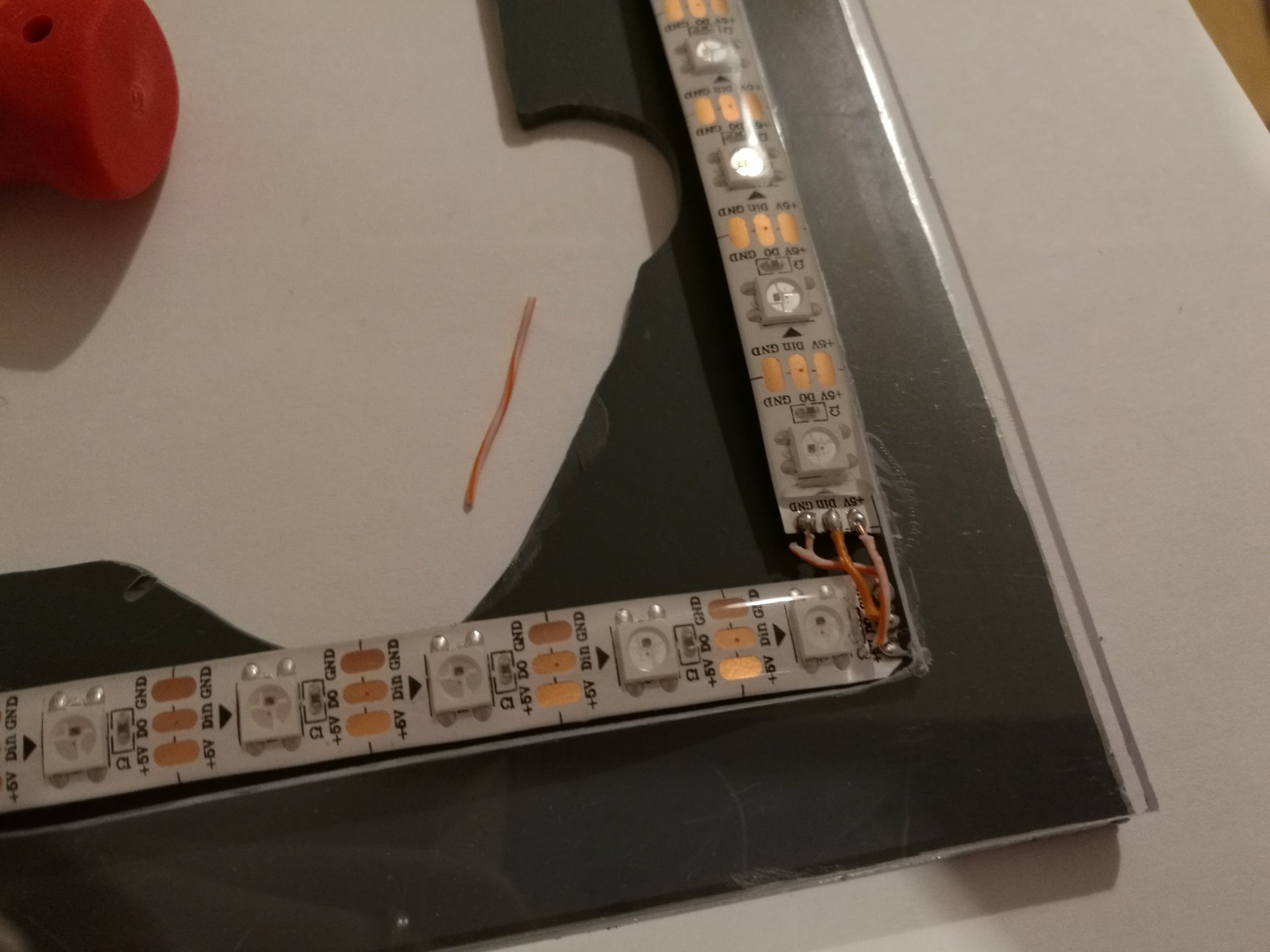
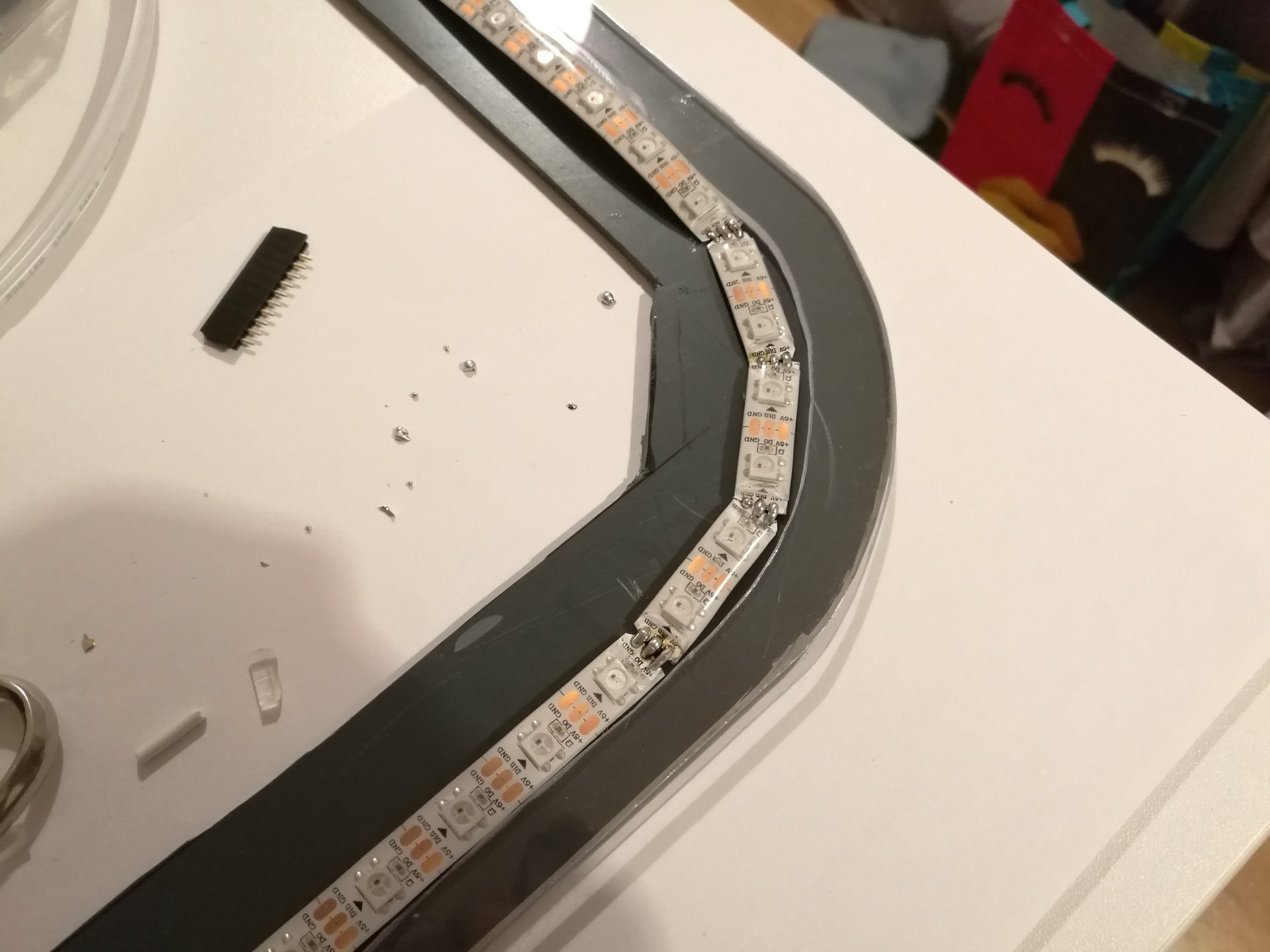
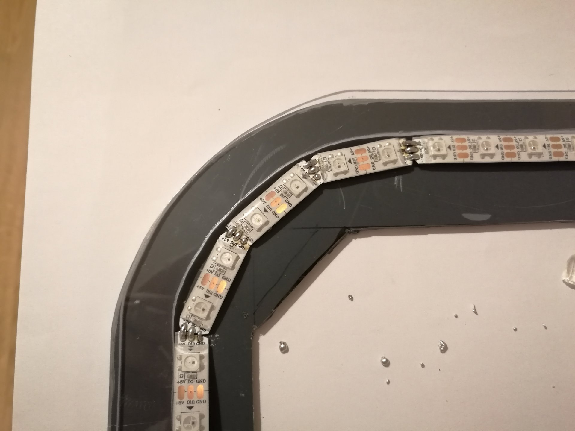
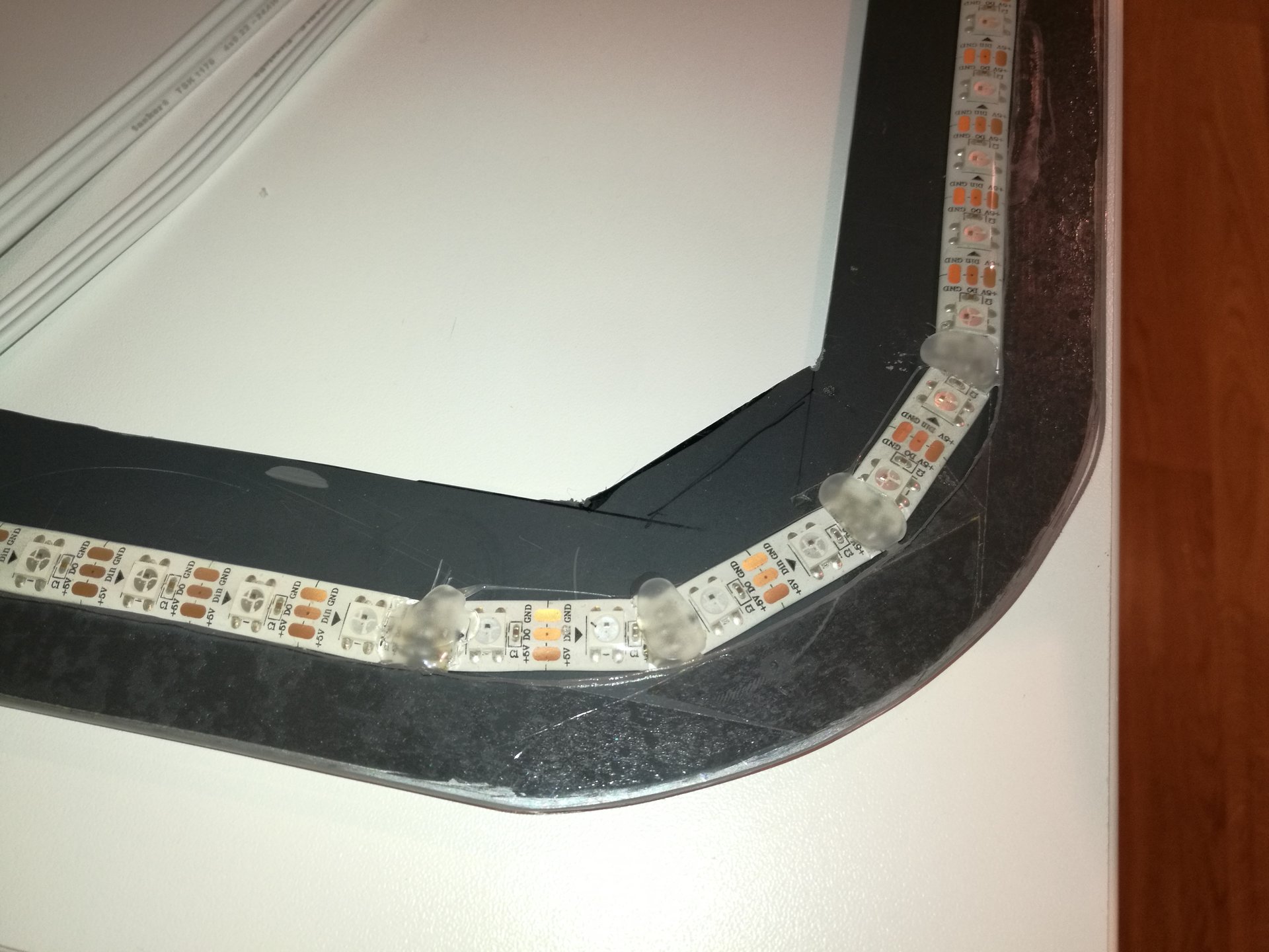
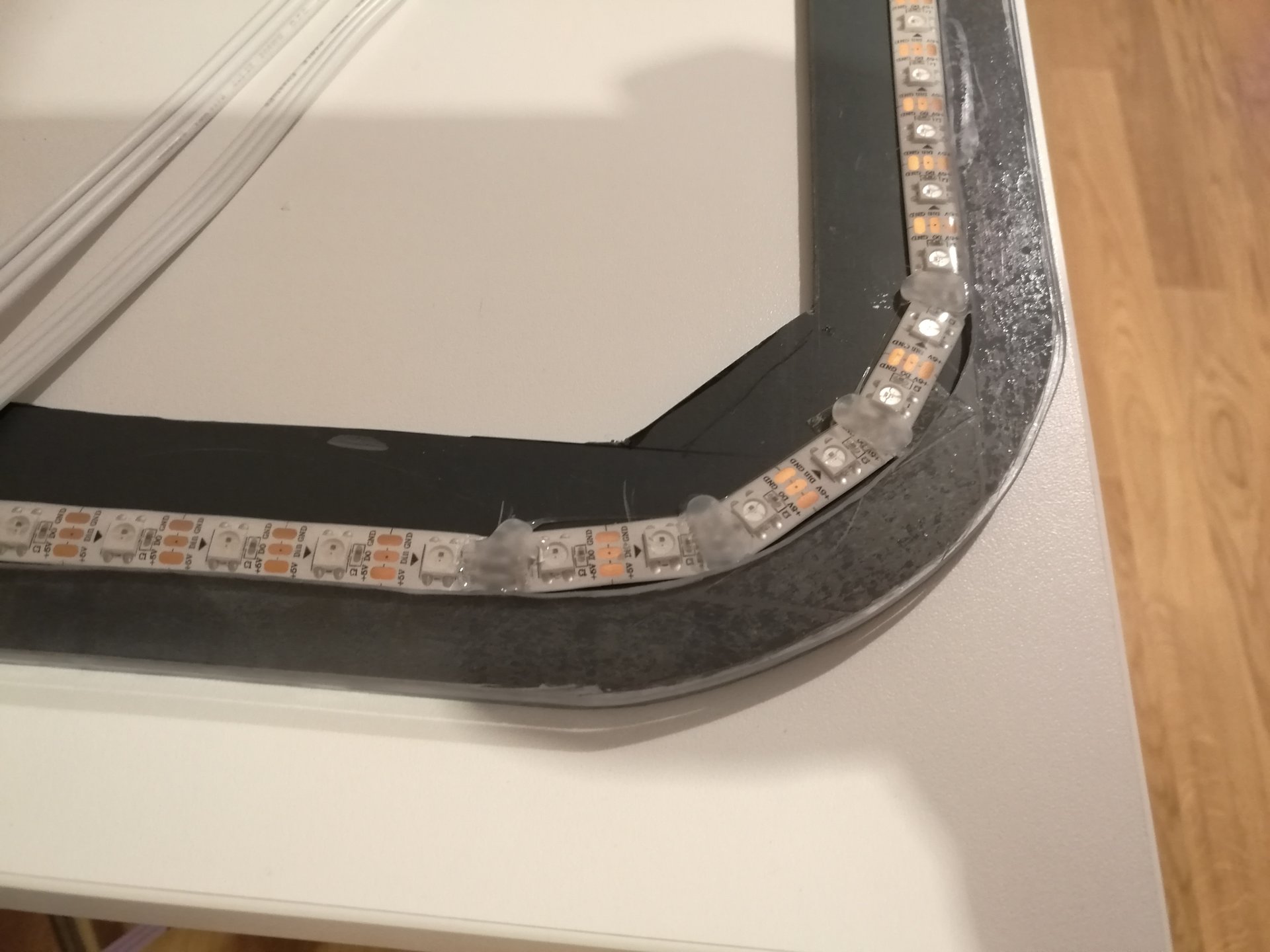
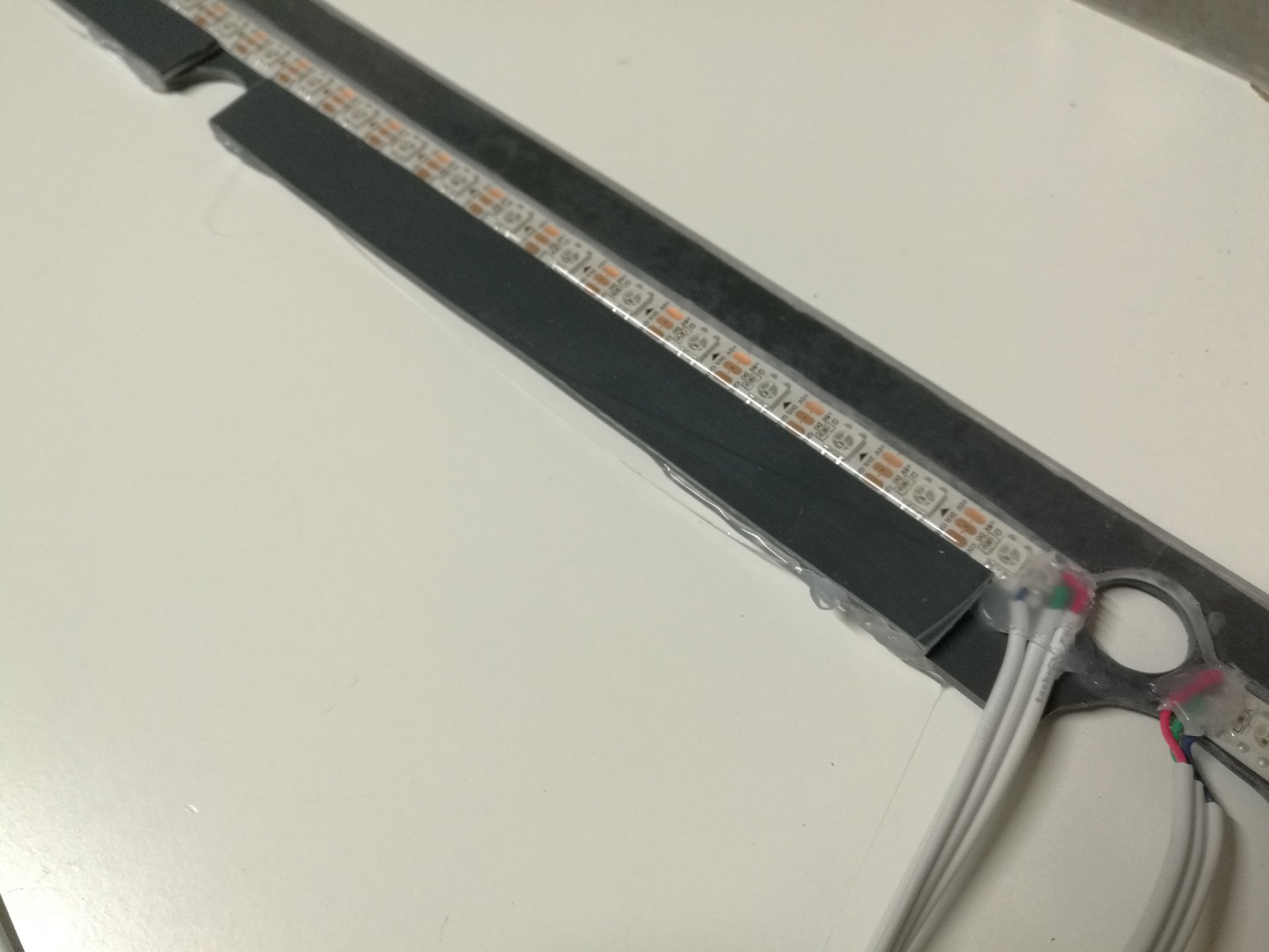
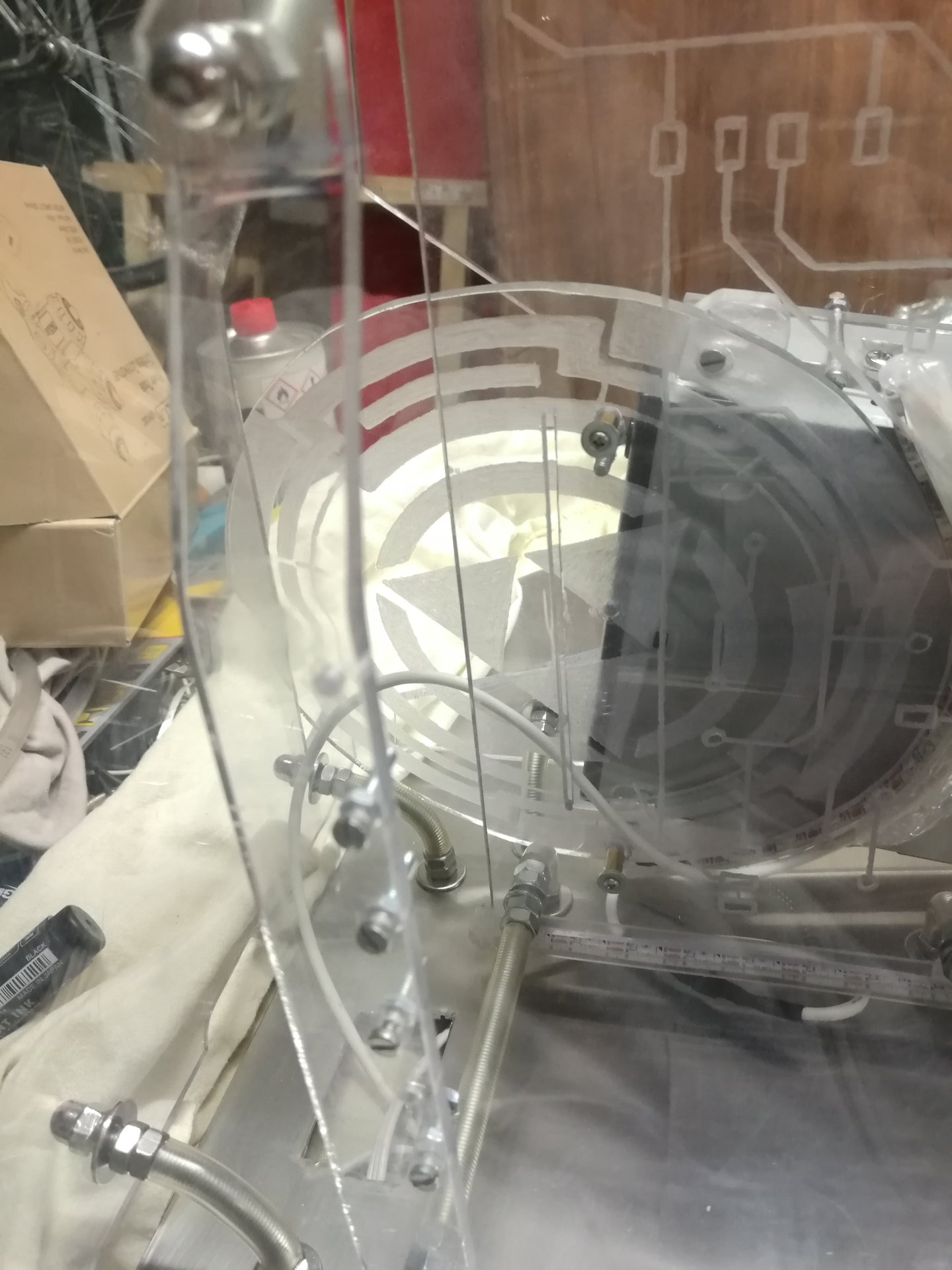
Some points have been particularly complicated, like the rounded corner of the base, in which I had to solder short strip pieces to make the curved strip:
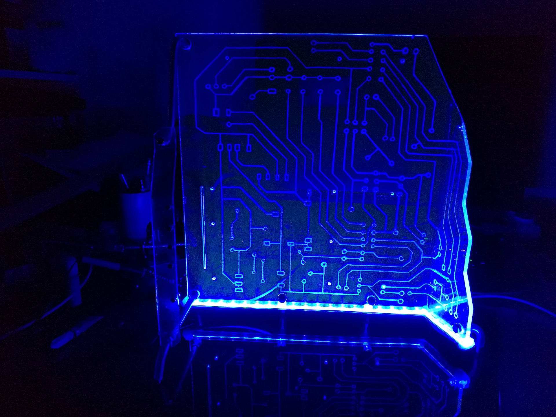
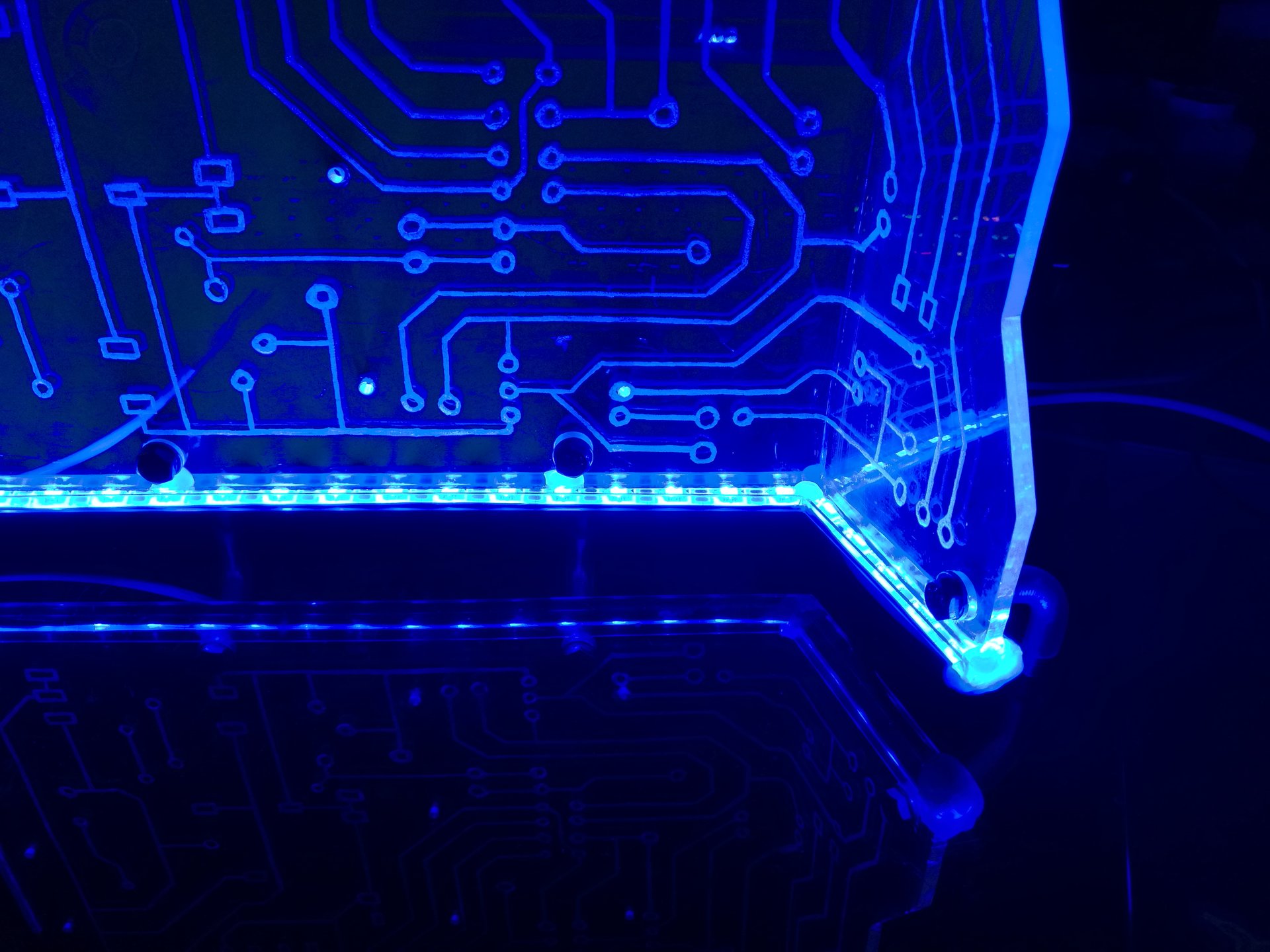
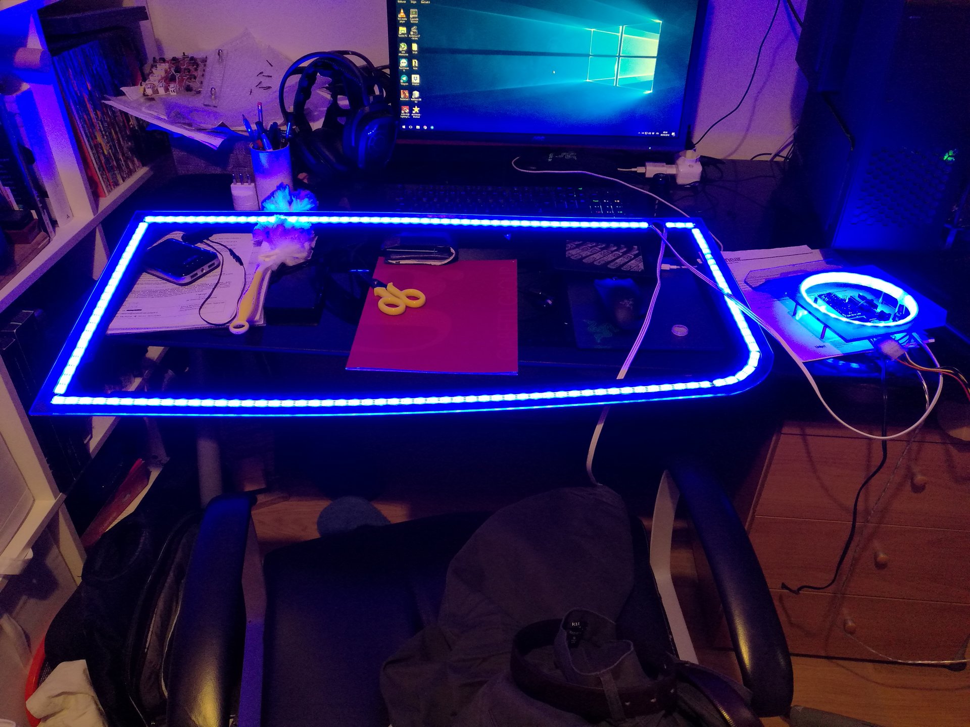
Two videos of the raw lighted frame (in the final position under the base, the led strip will not be visible like the one in this videos. The only visible part will be the lighted external edge of the polycarbonate frame):
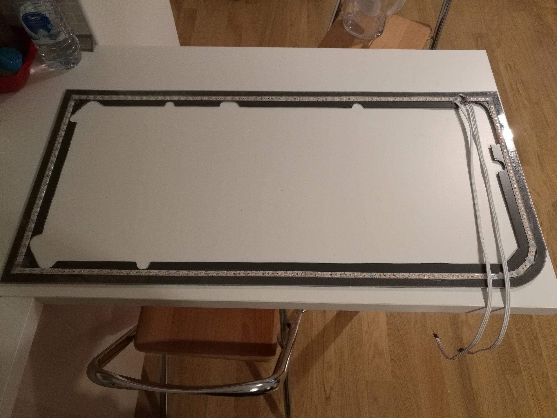
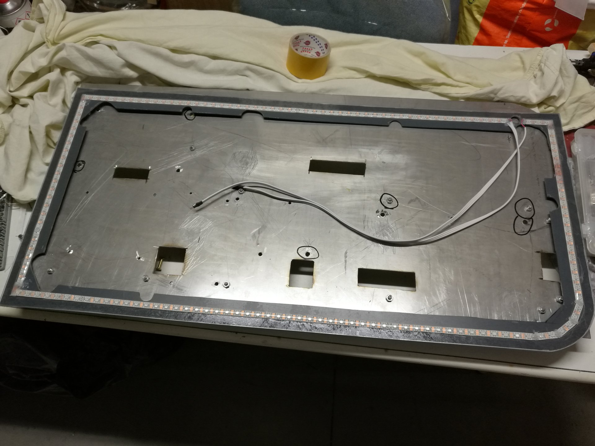
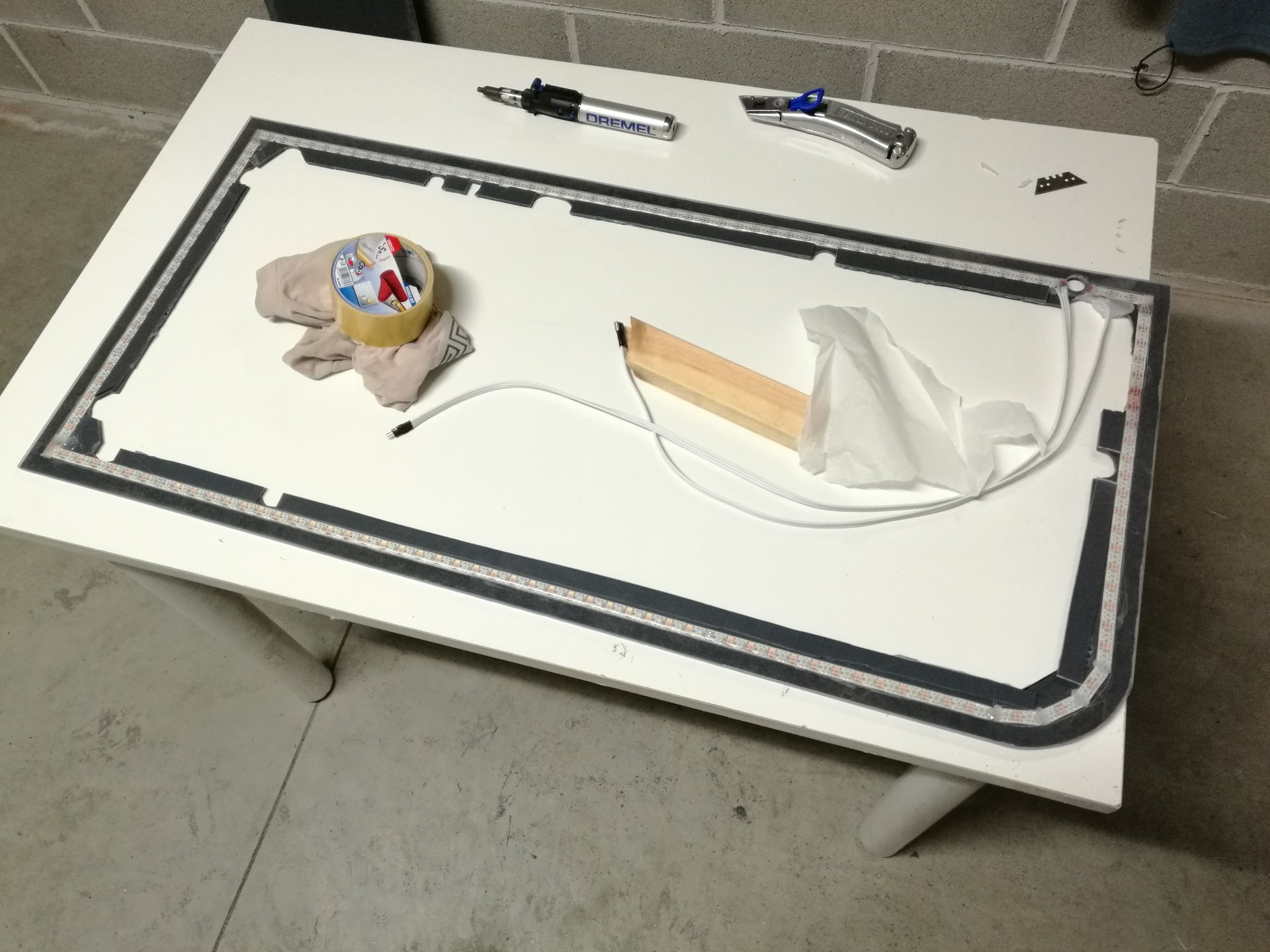
After soldering the led strips and attaching the two frames together with some biadhesive tape, now I must assemble it under the steel base (I have added some pieces of grey PVC in the inner side of the frame, to avoid light leaks towards the center):
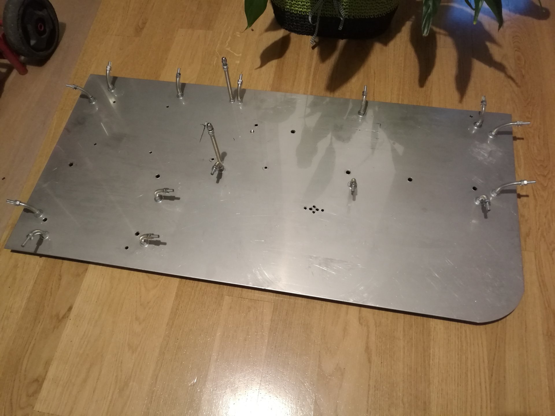
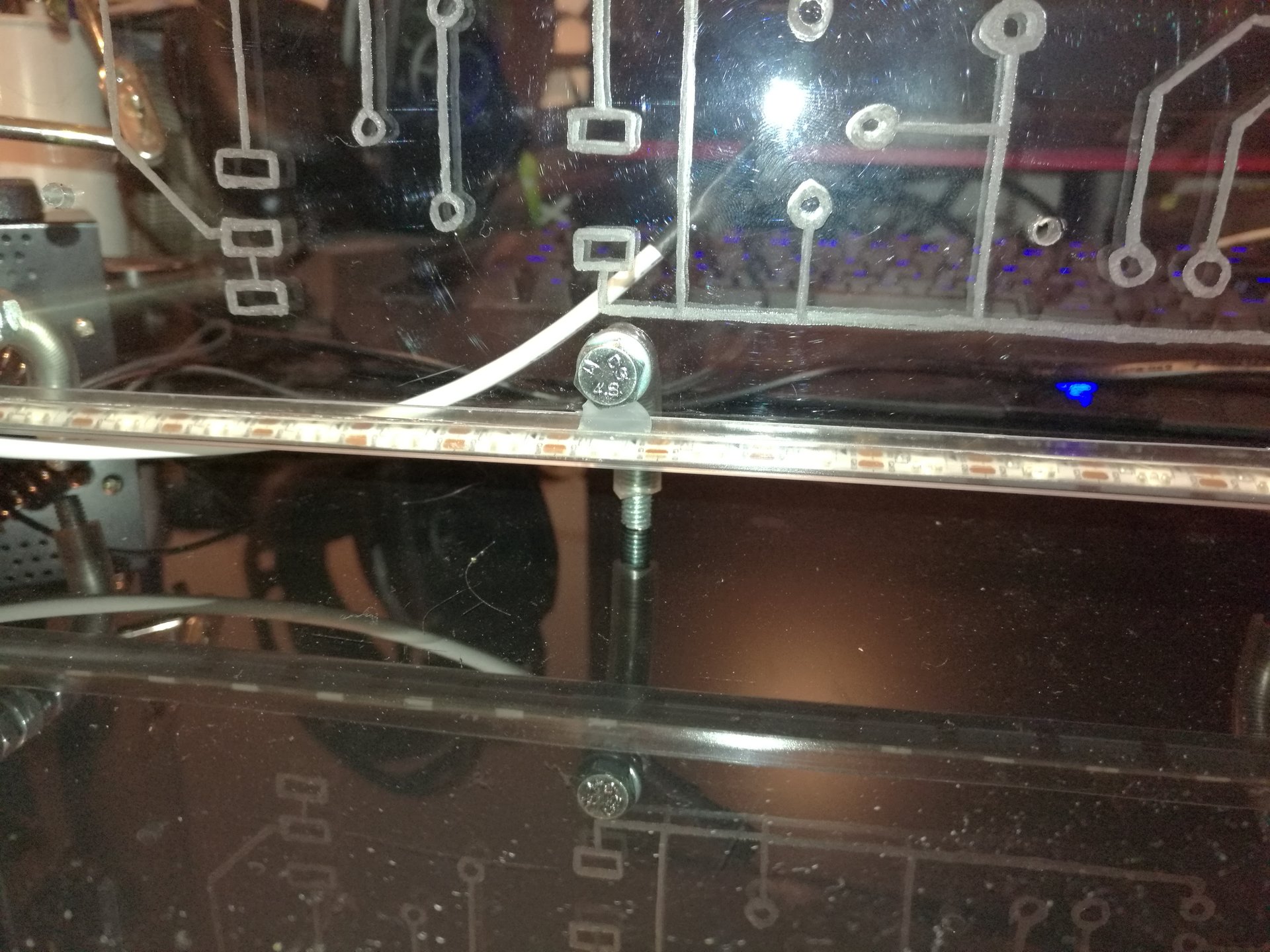
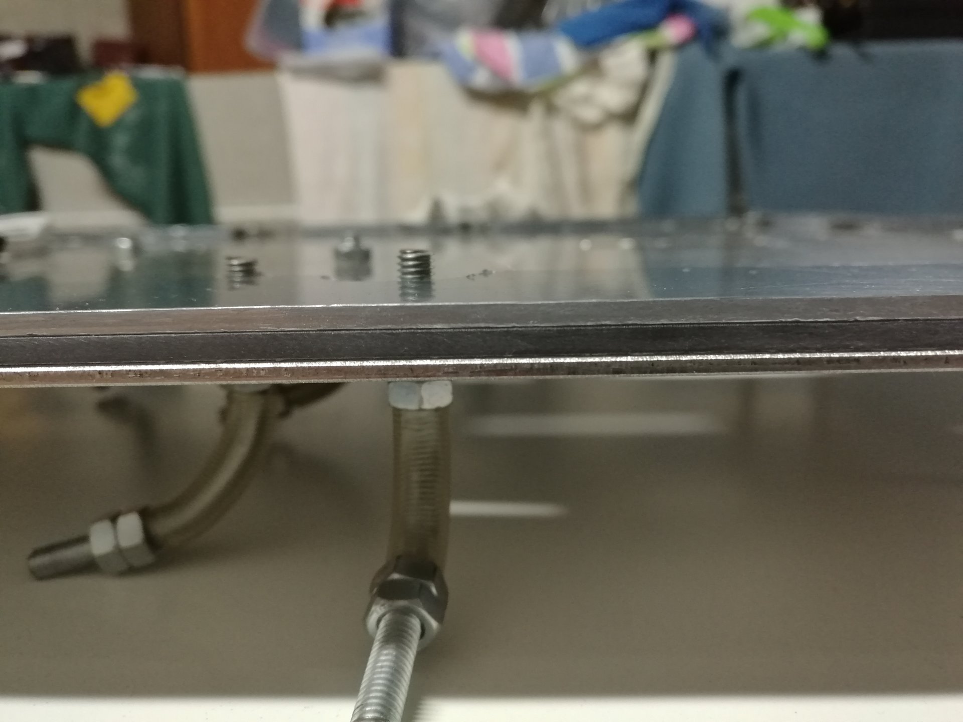
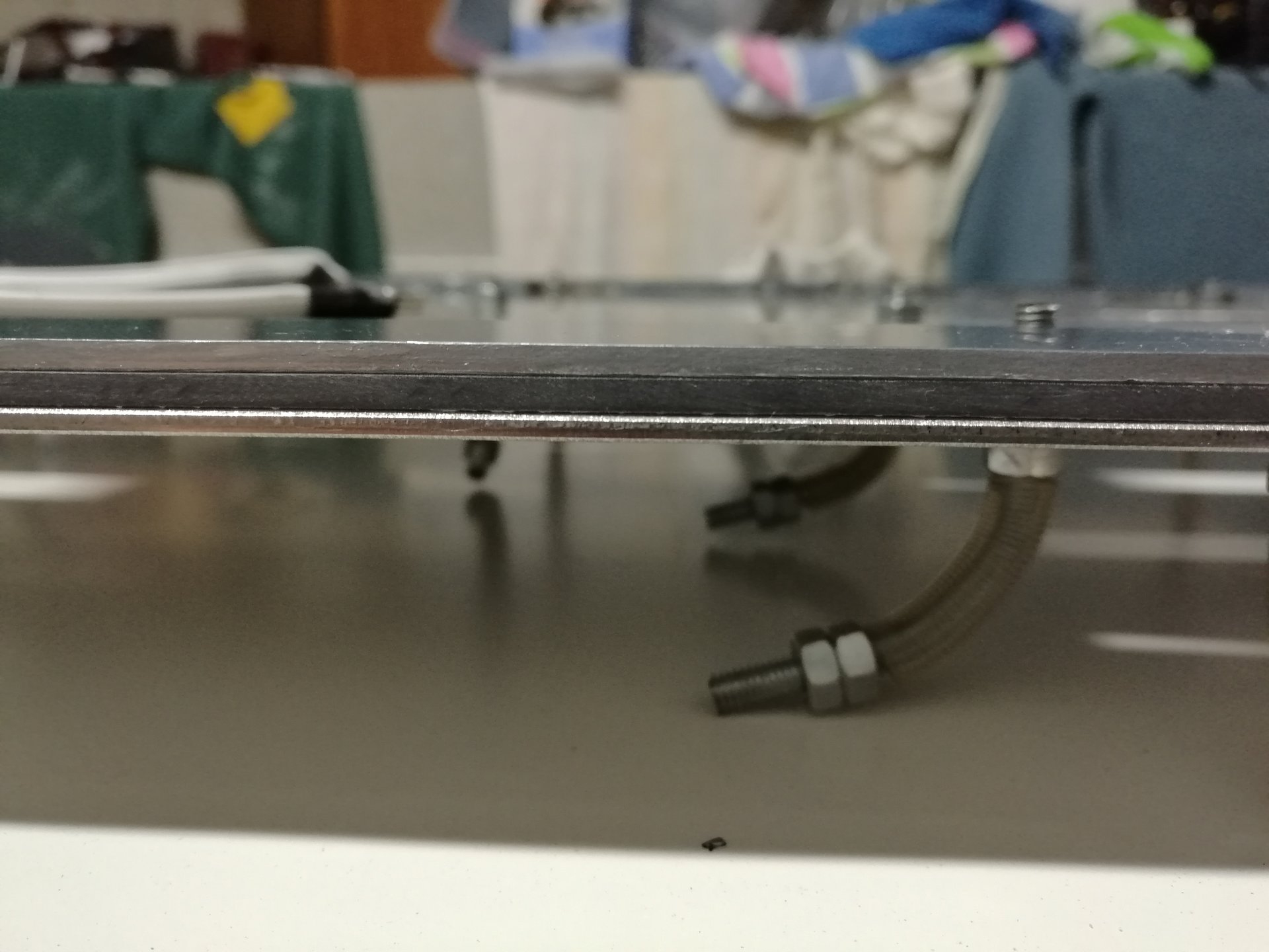
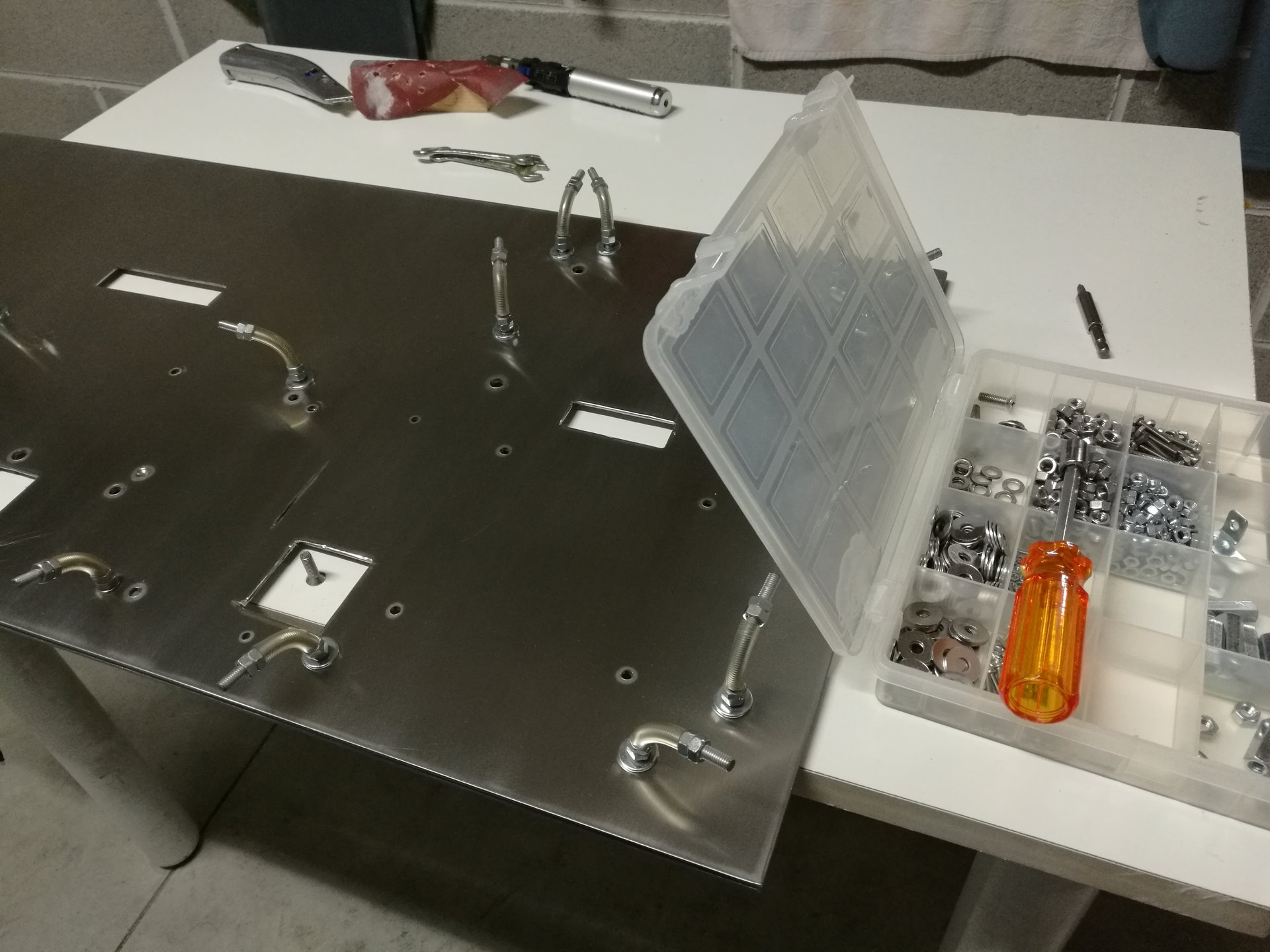
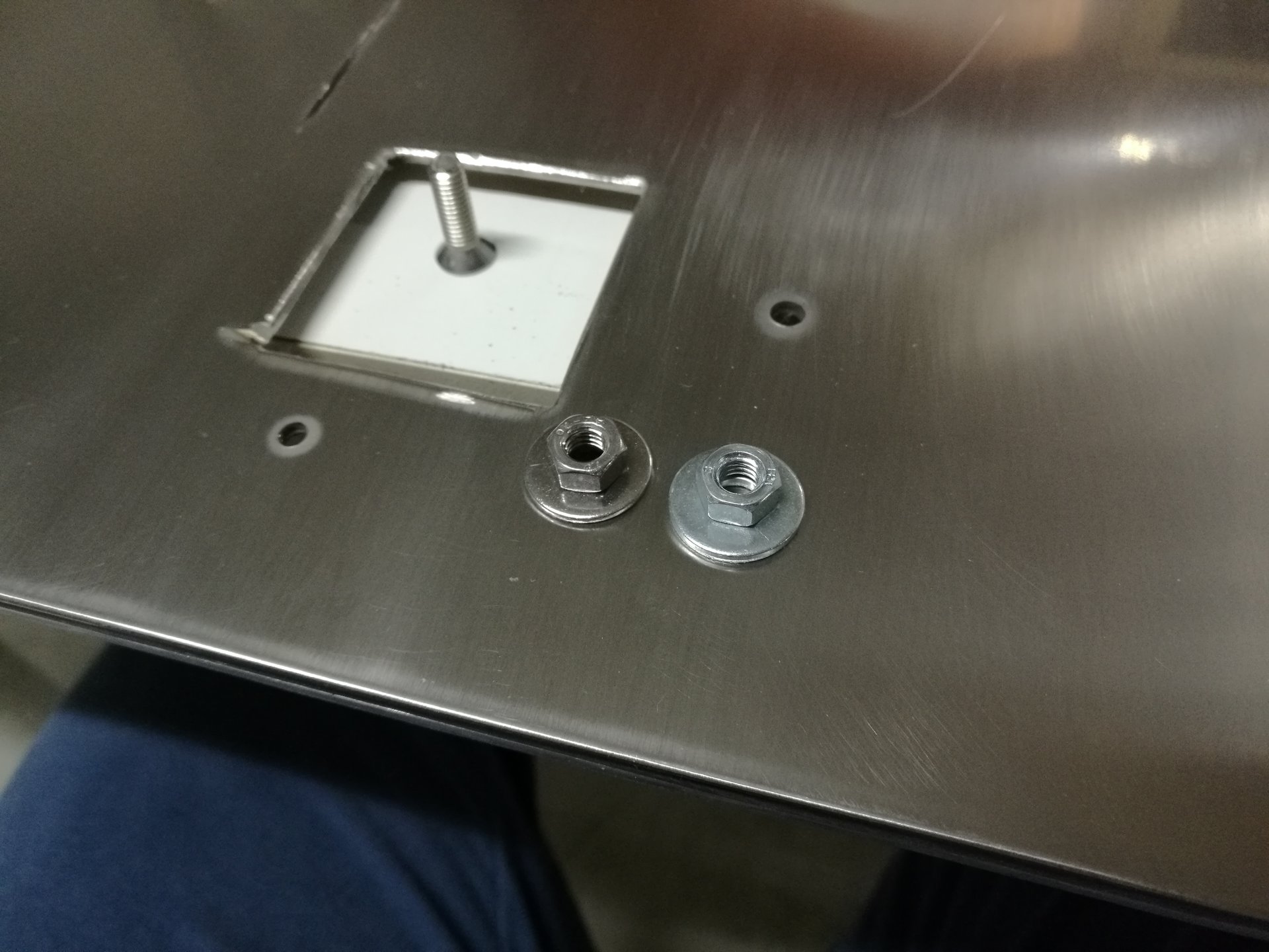
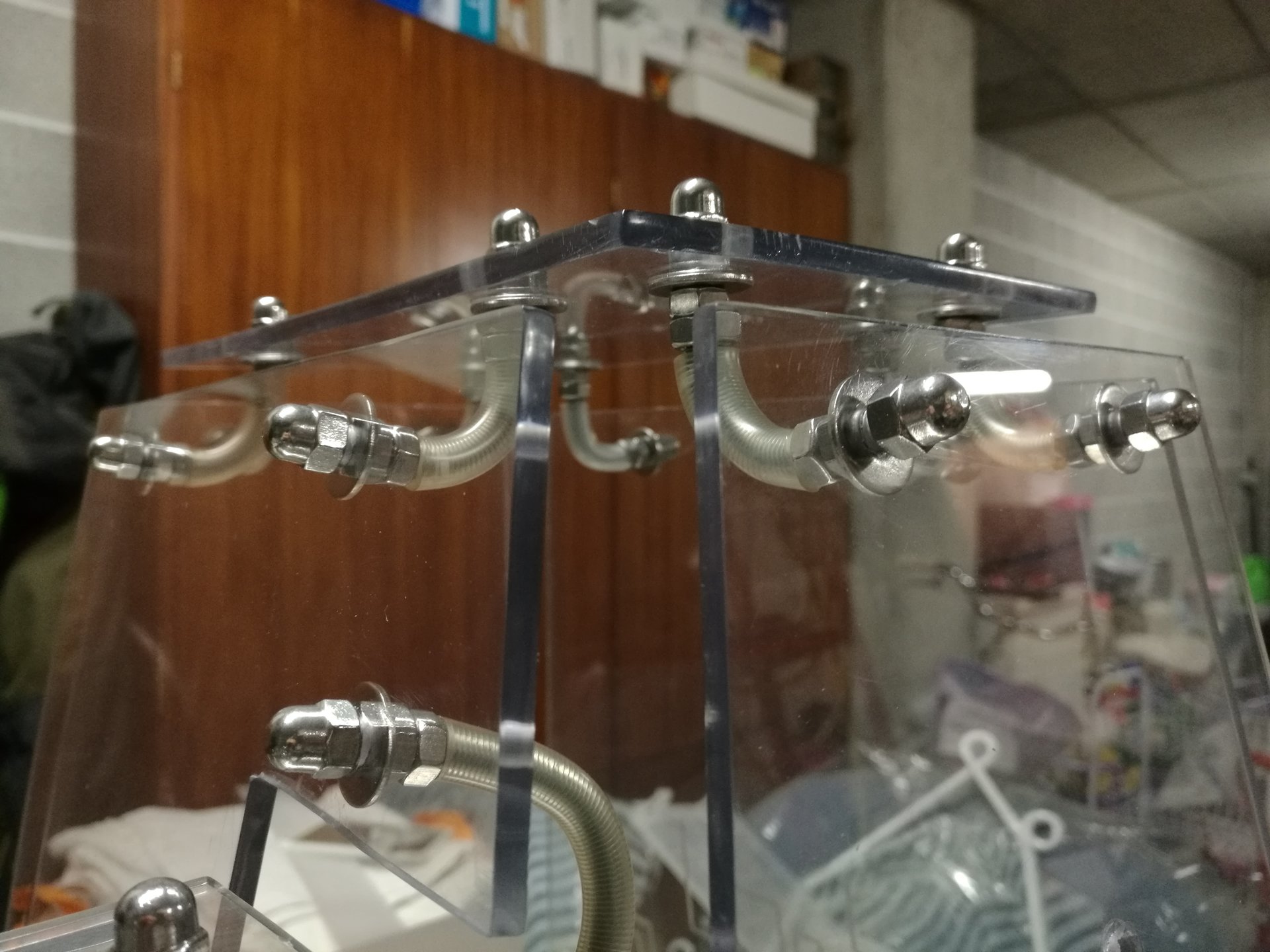
Meanwhile I have replaced all the old nuts and washers, with stainless steel ones:
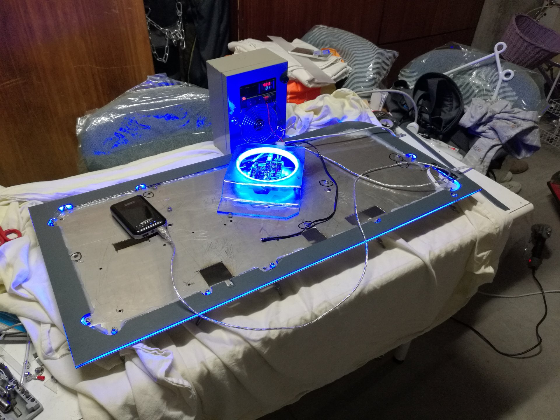
And this is a lighting test of the base (up side down):
▲ Interspace for the cables and reassembling the case
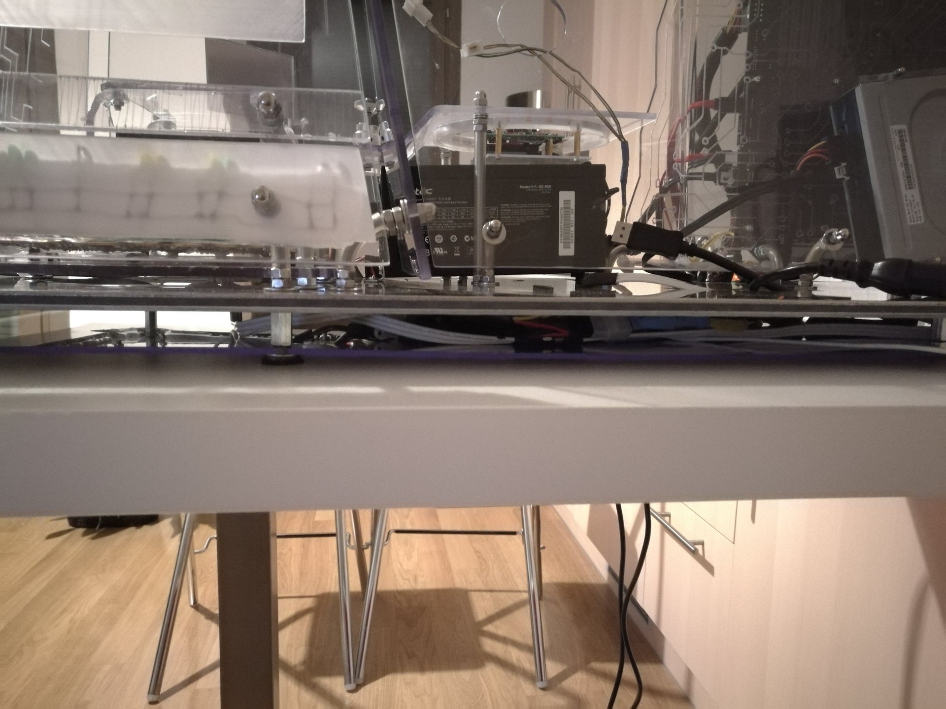
After completing the base, I have made the bottom panel that keeps in place all the cables in the interspace under the base.
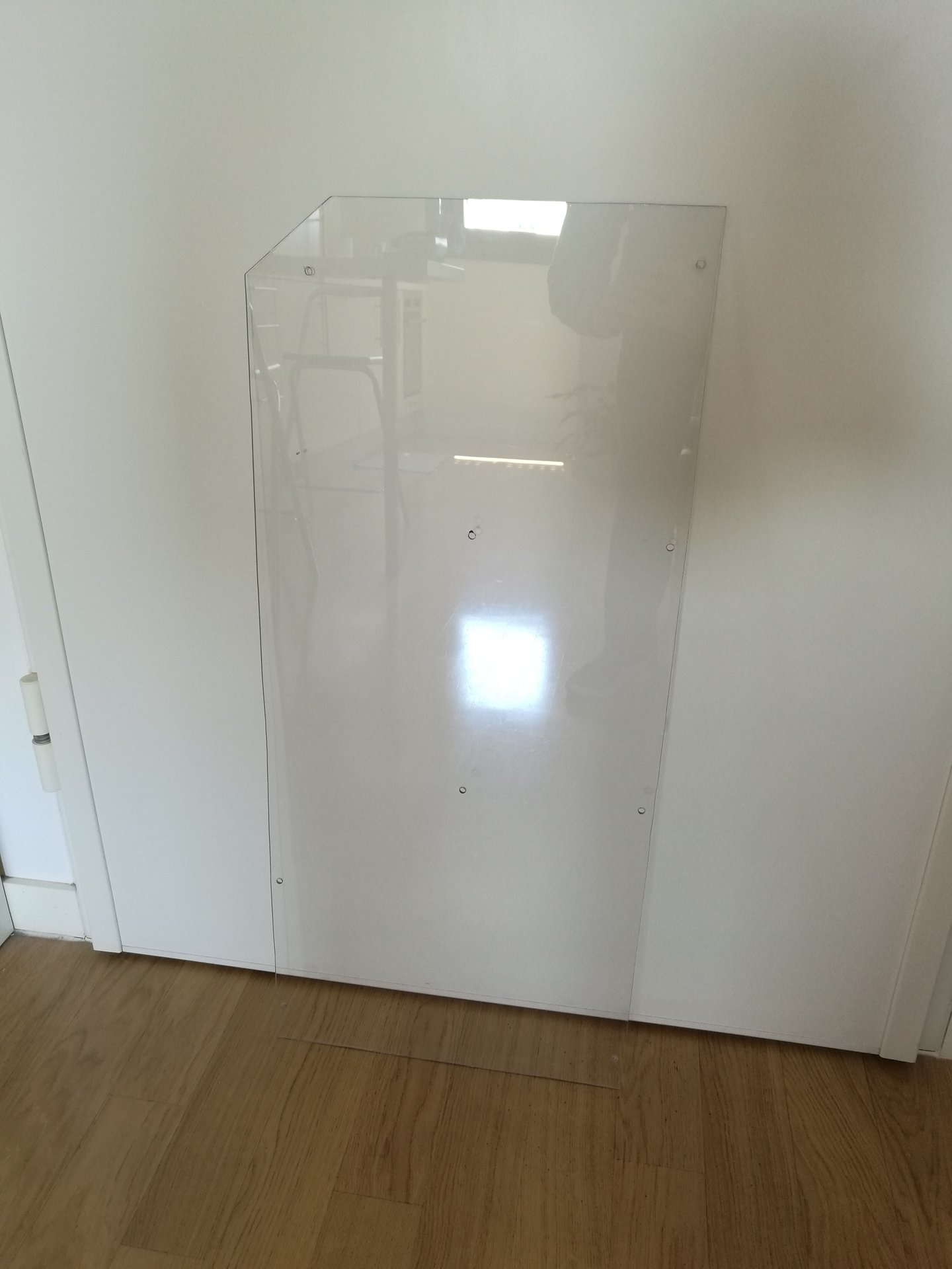
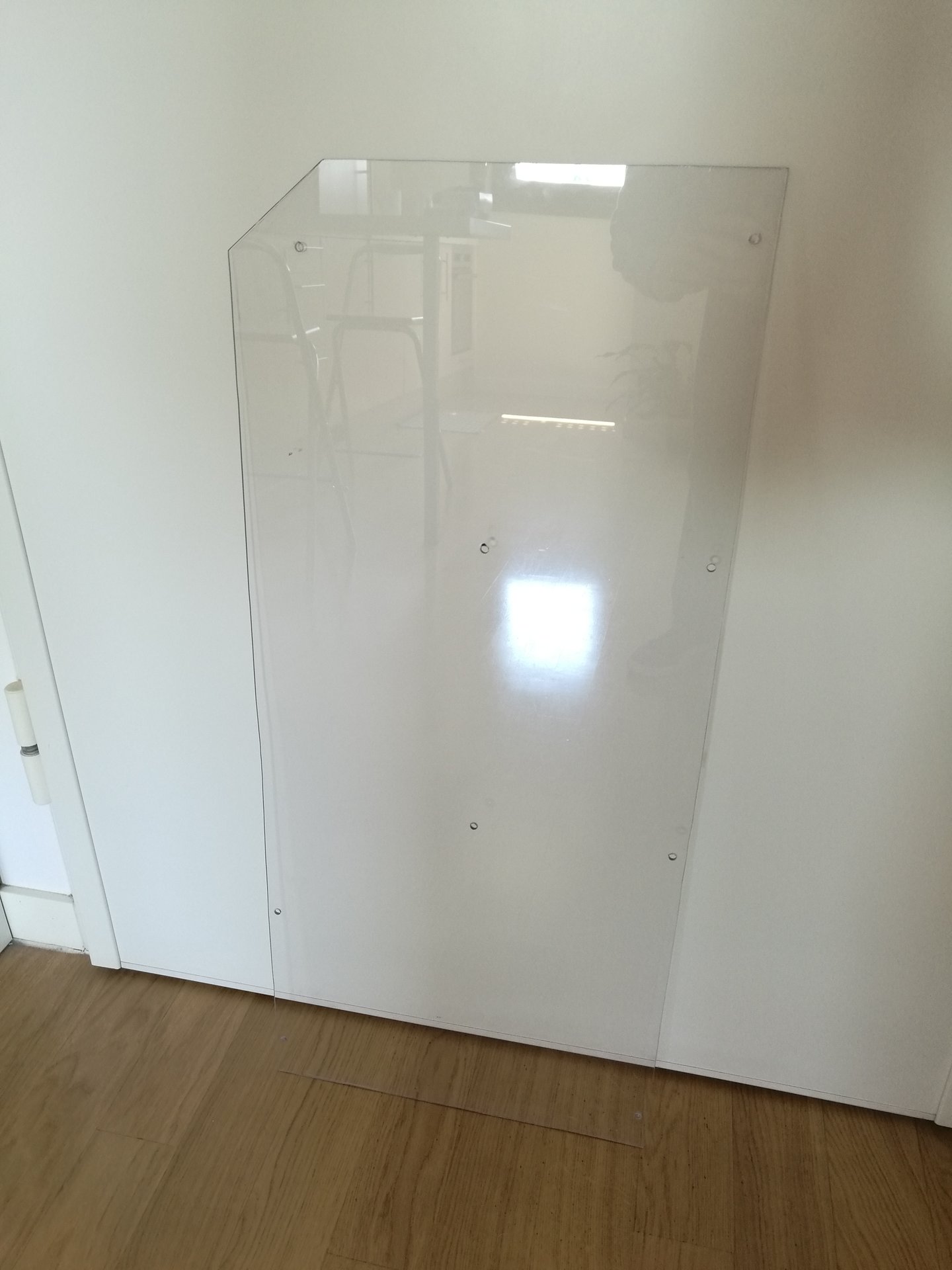
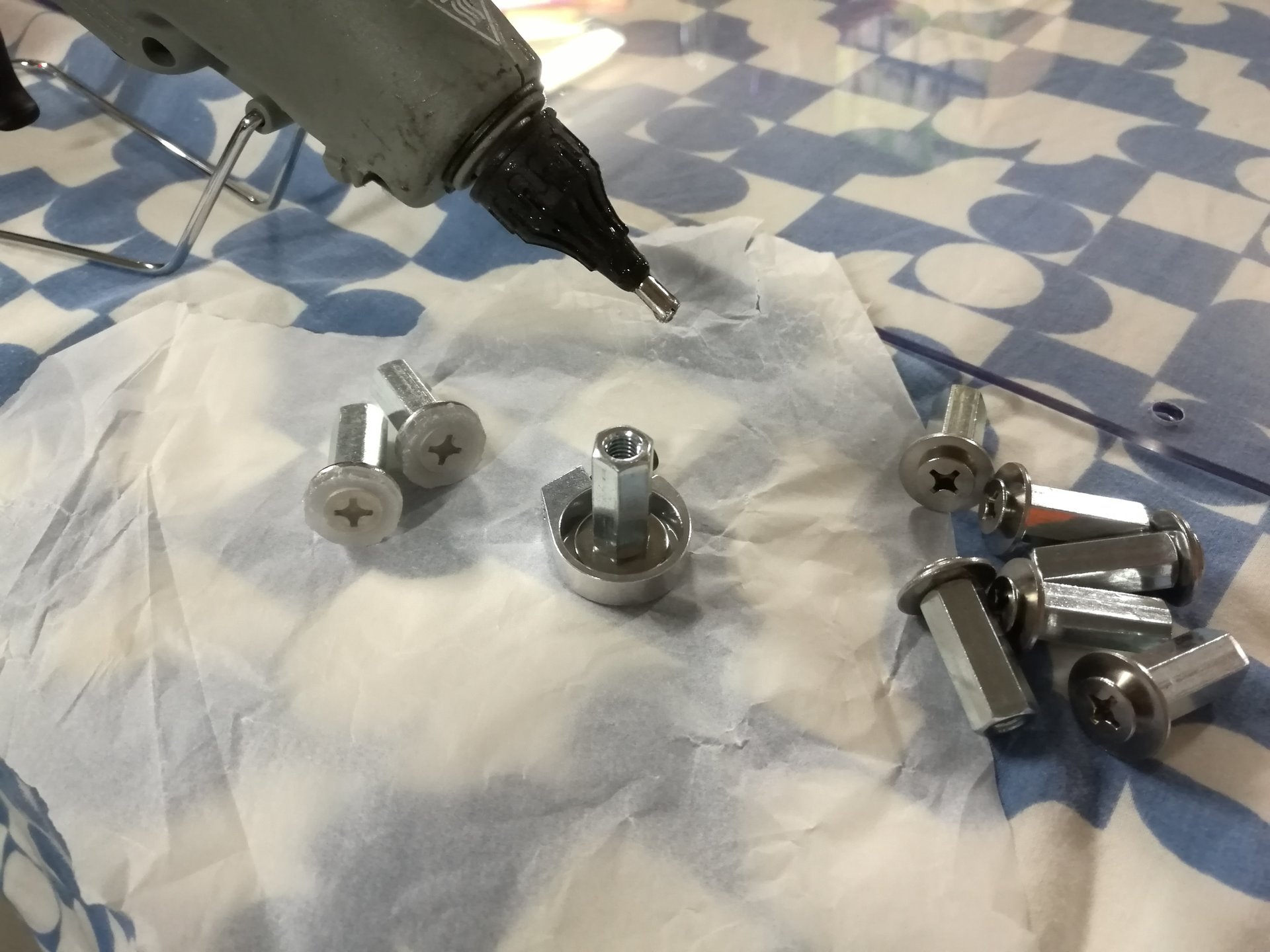
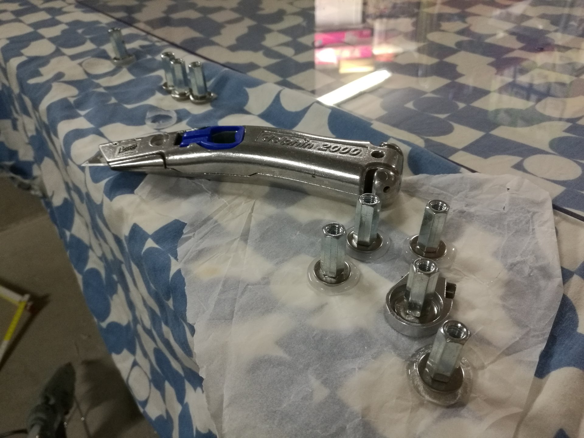
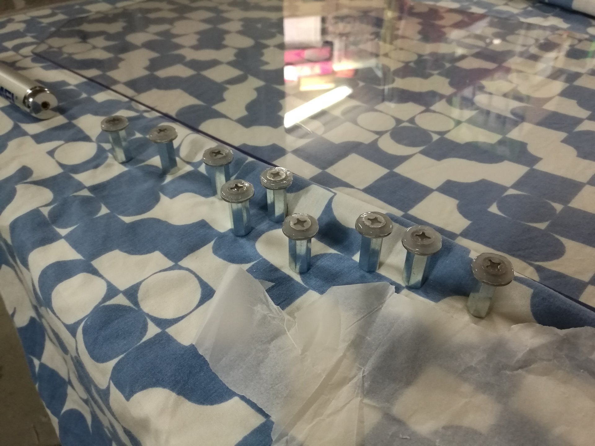
I wanted to make it as invisible as possible, so I used a trasparent polycarbonate panel, fixed under the base by some 25mm high junction nuts.
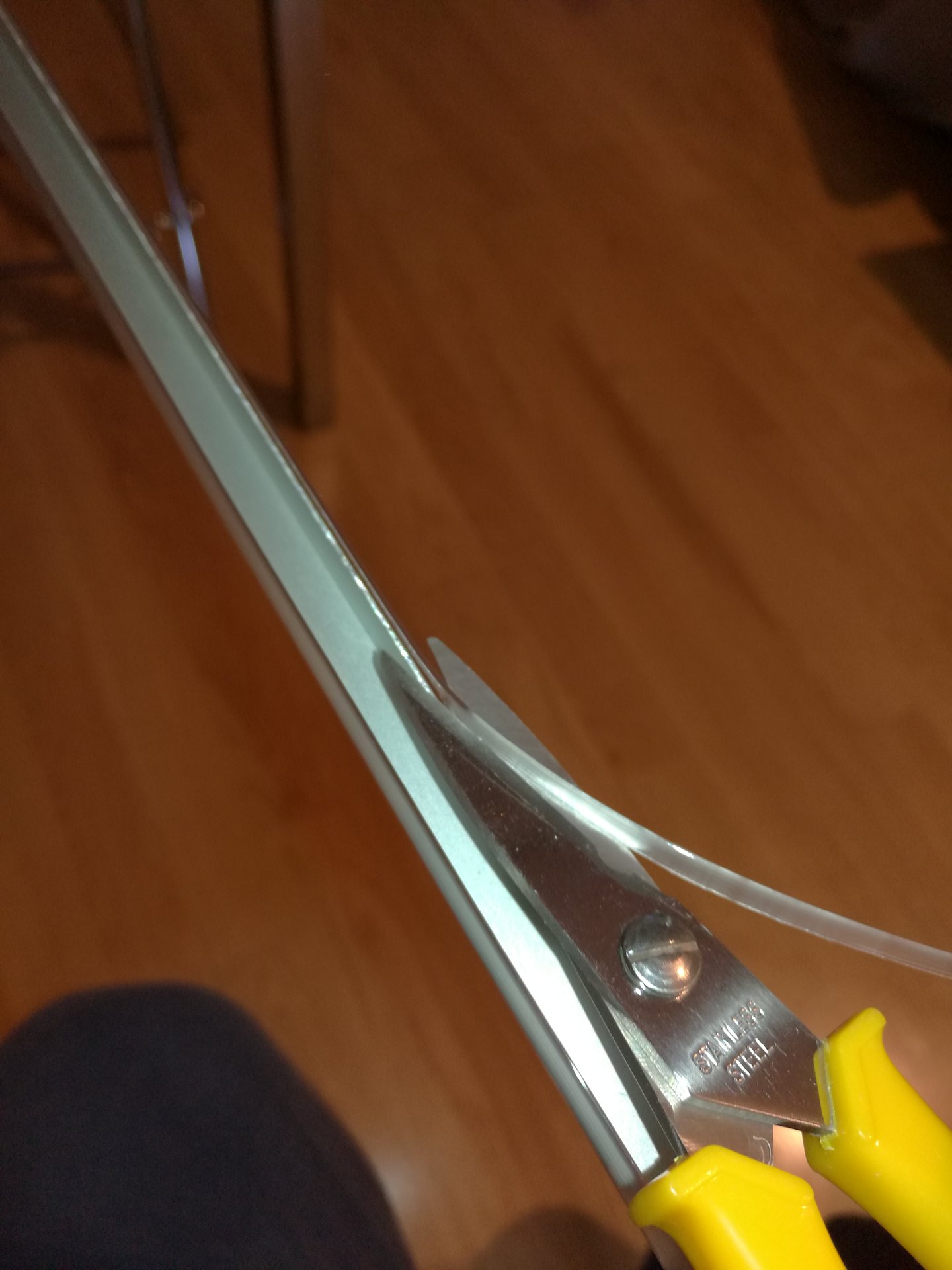
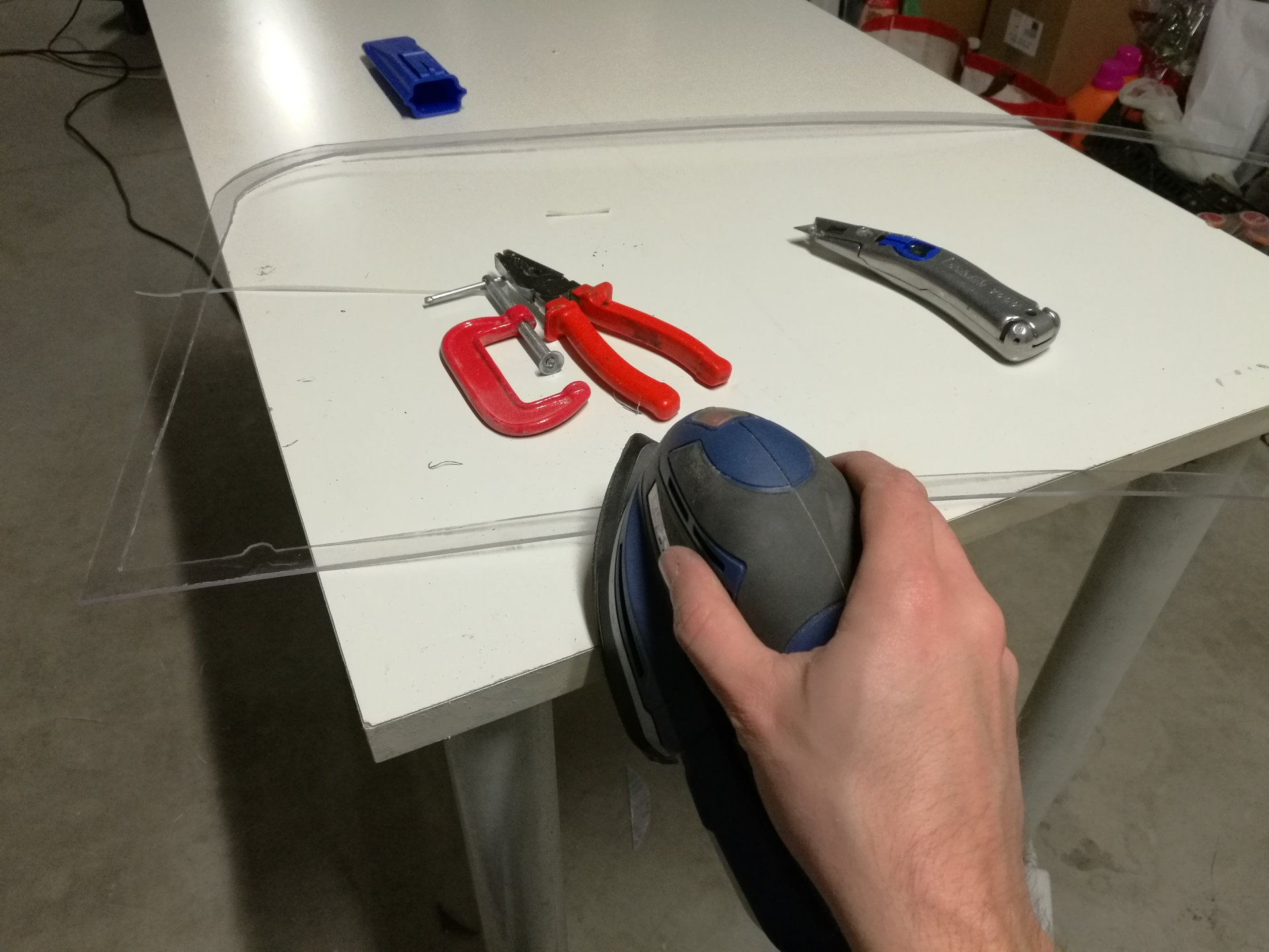
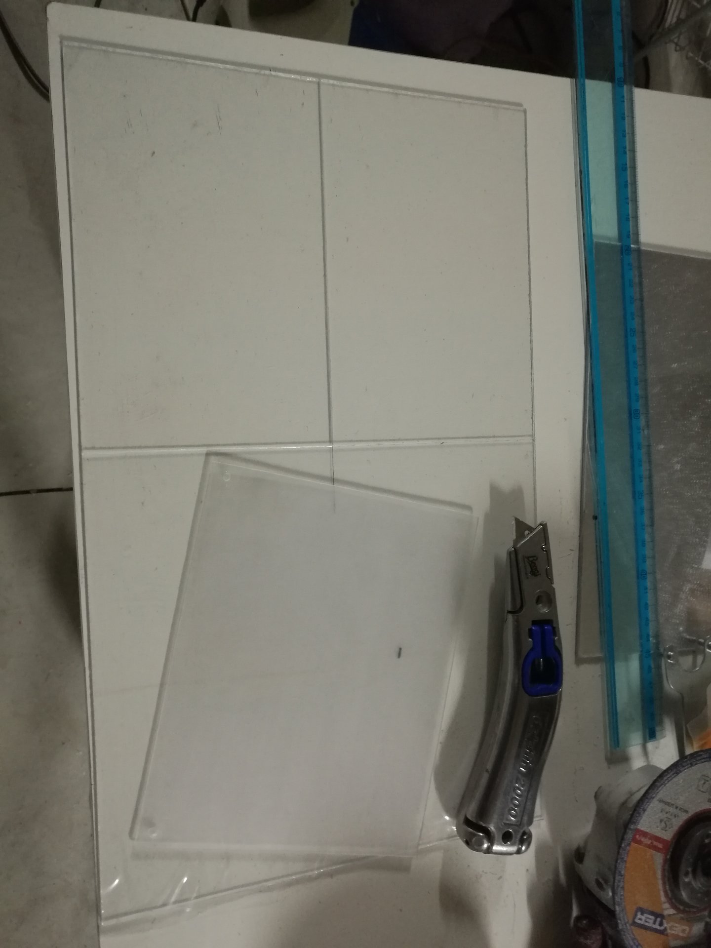
Here I’m taking the measures and cutting the panel:
These bolts have two purposes: they fix the panel to the junction nuts, but they also serve as feet for the case (putting felt pads on the bolts’ heads):
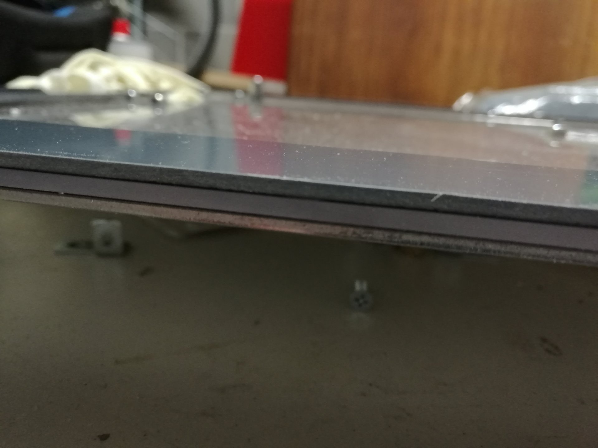
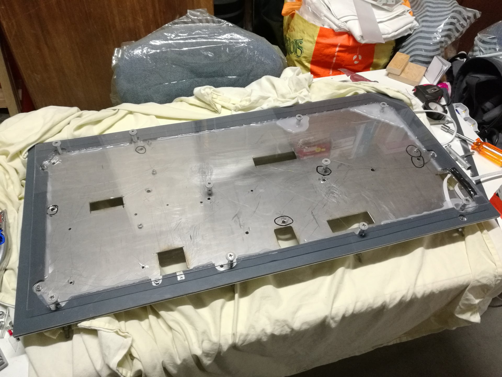
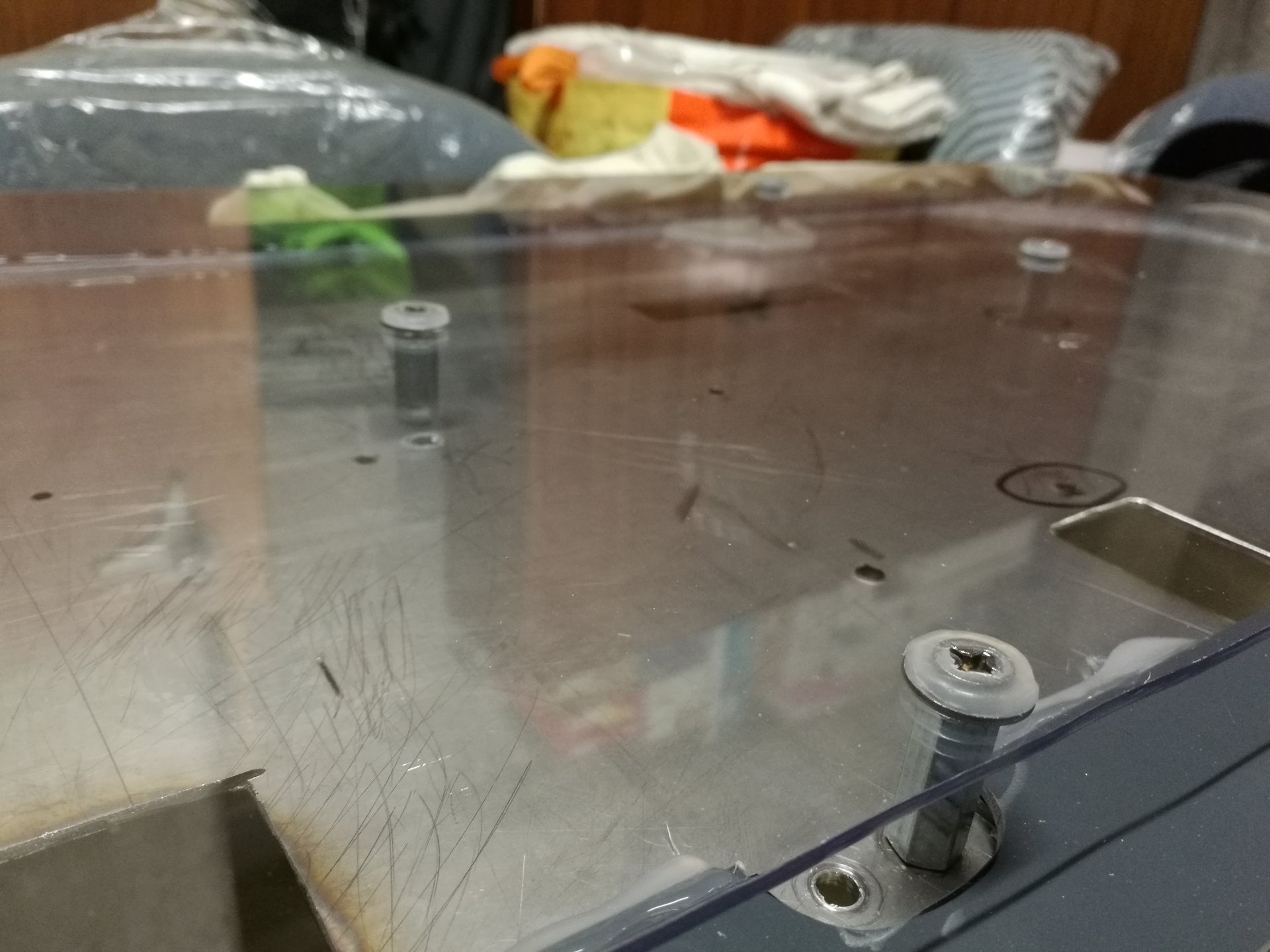
I mount the panel under the base:
And this is how the panel appears from above, it is almost invisible:
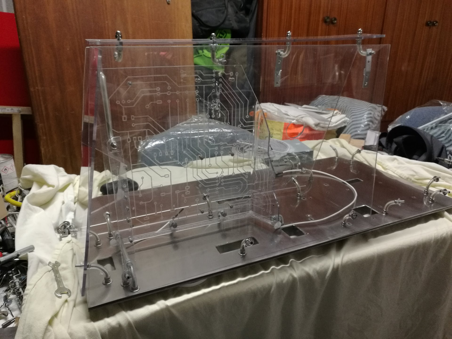
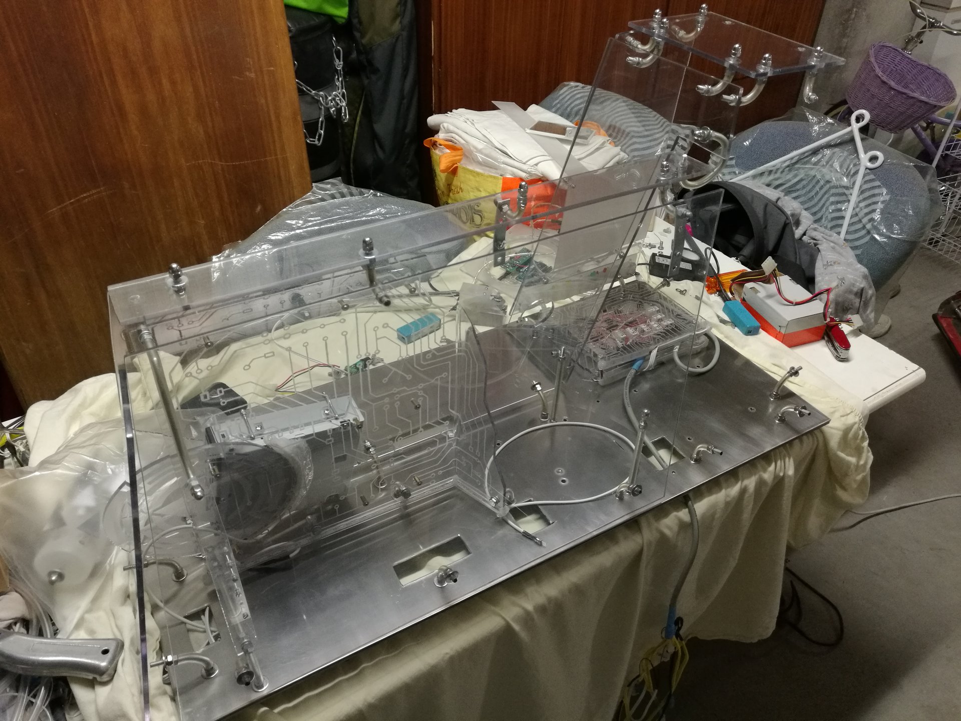
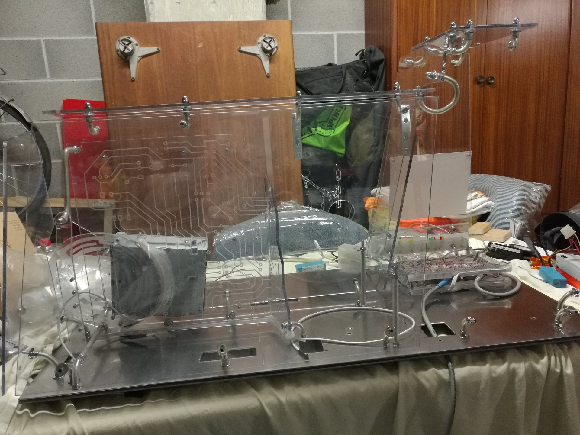
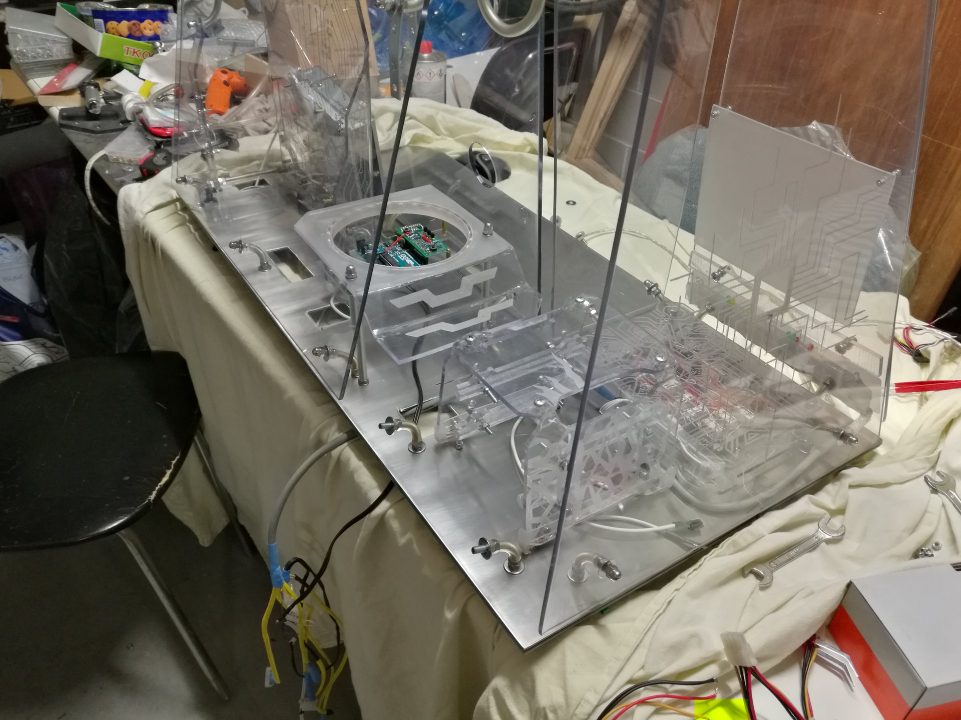
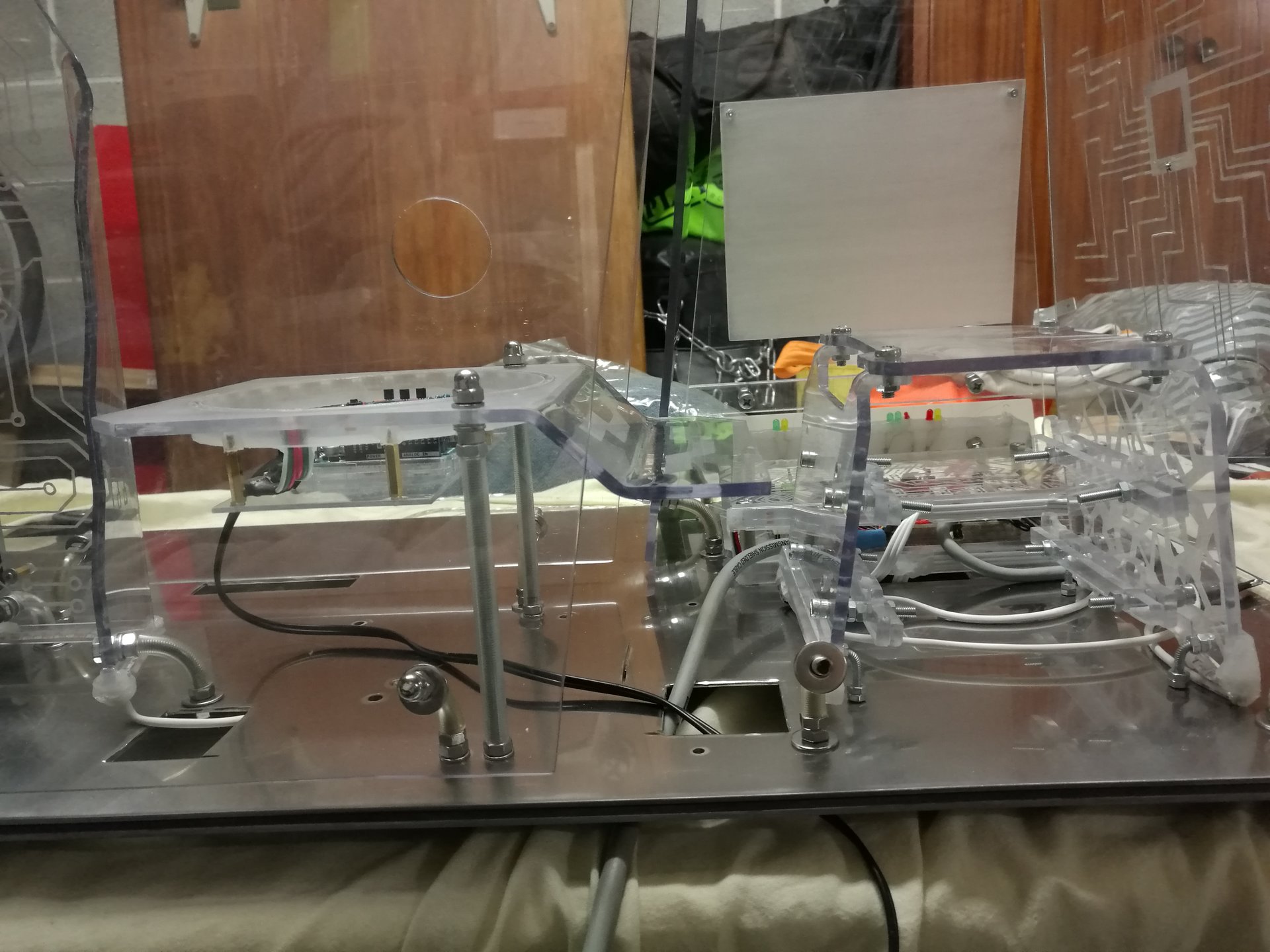
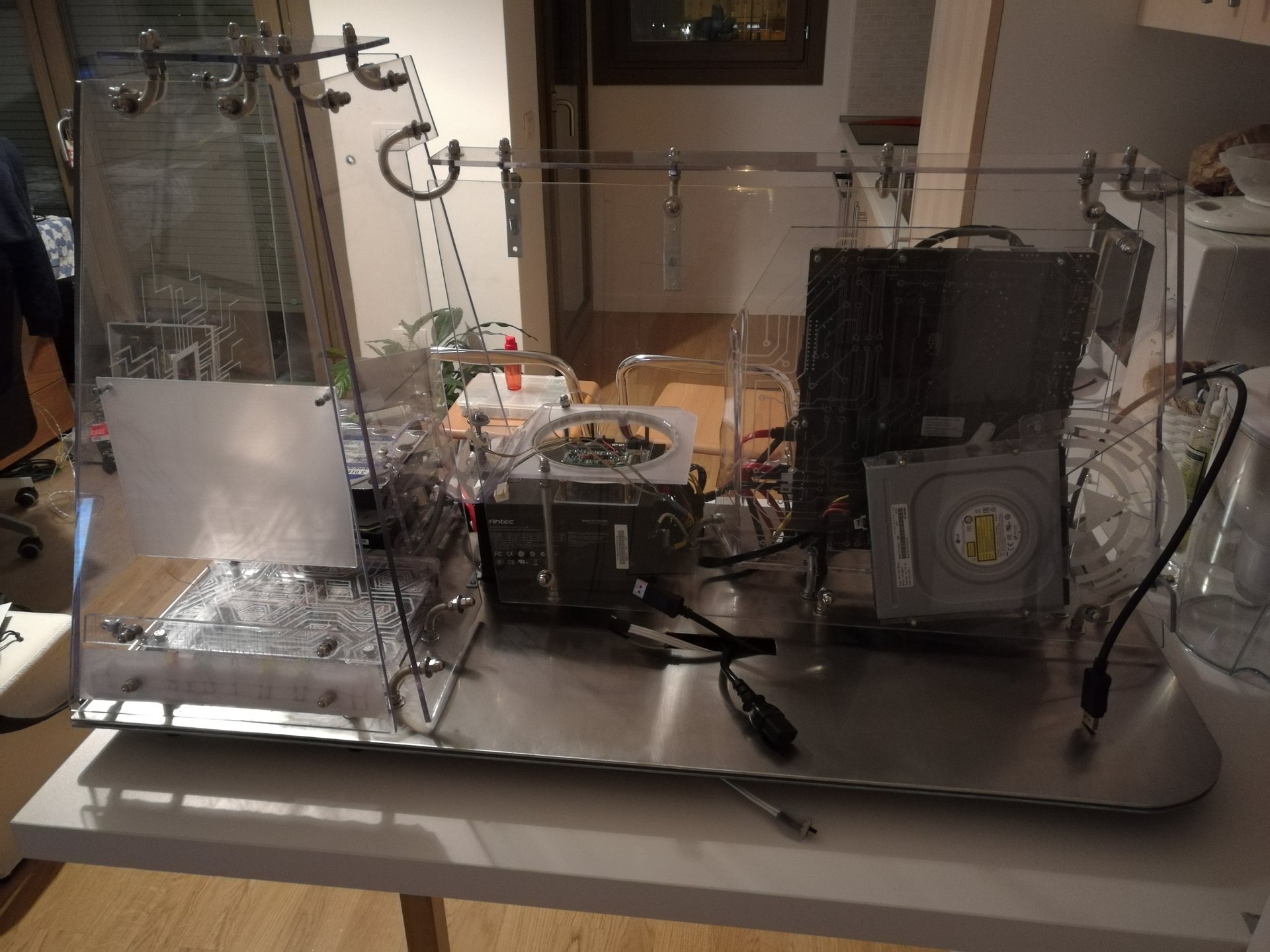
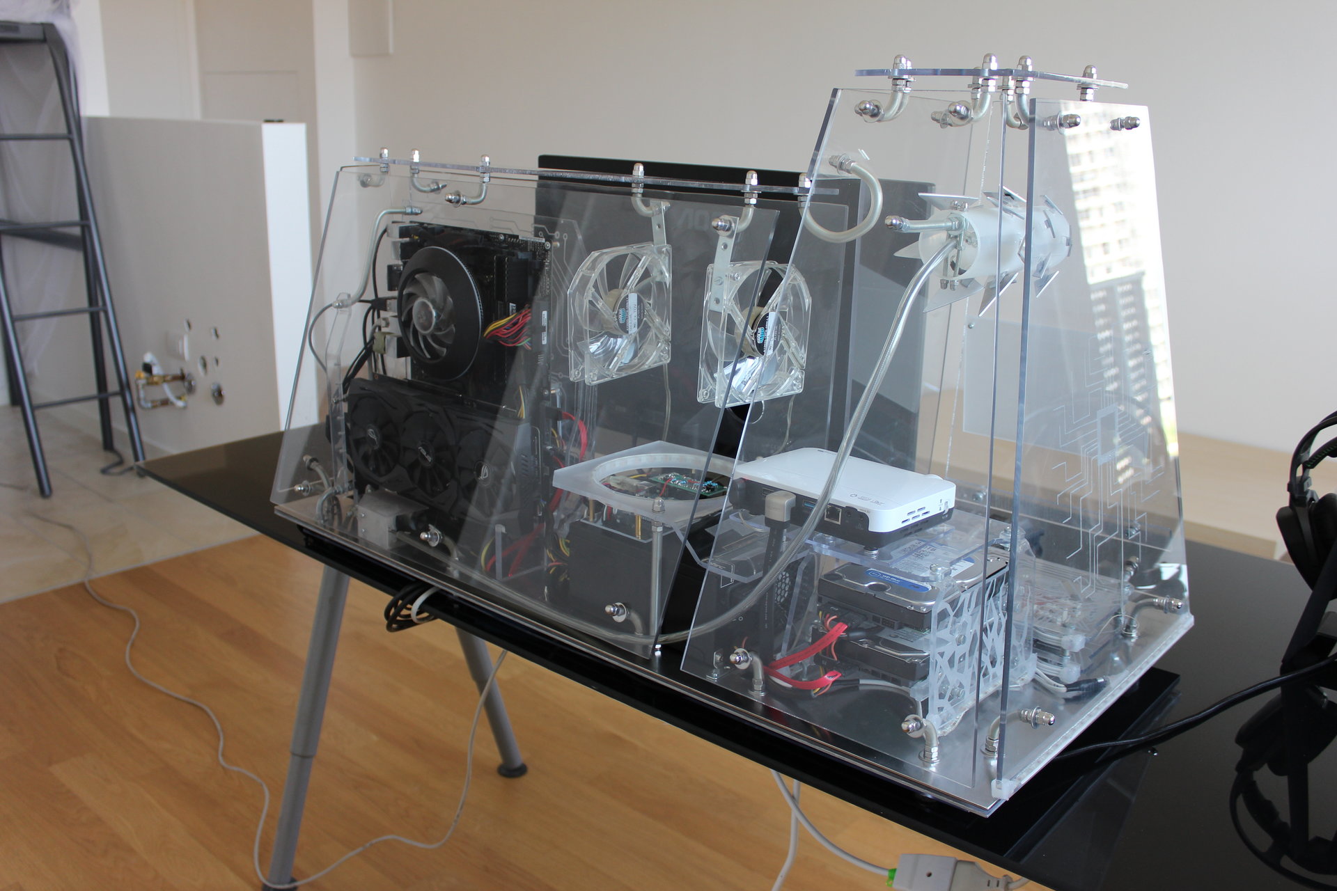
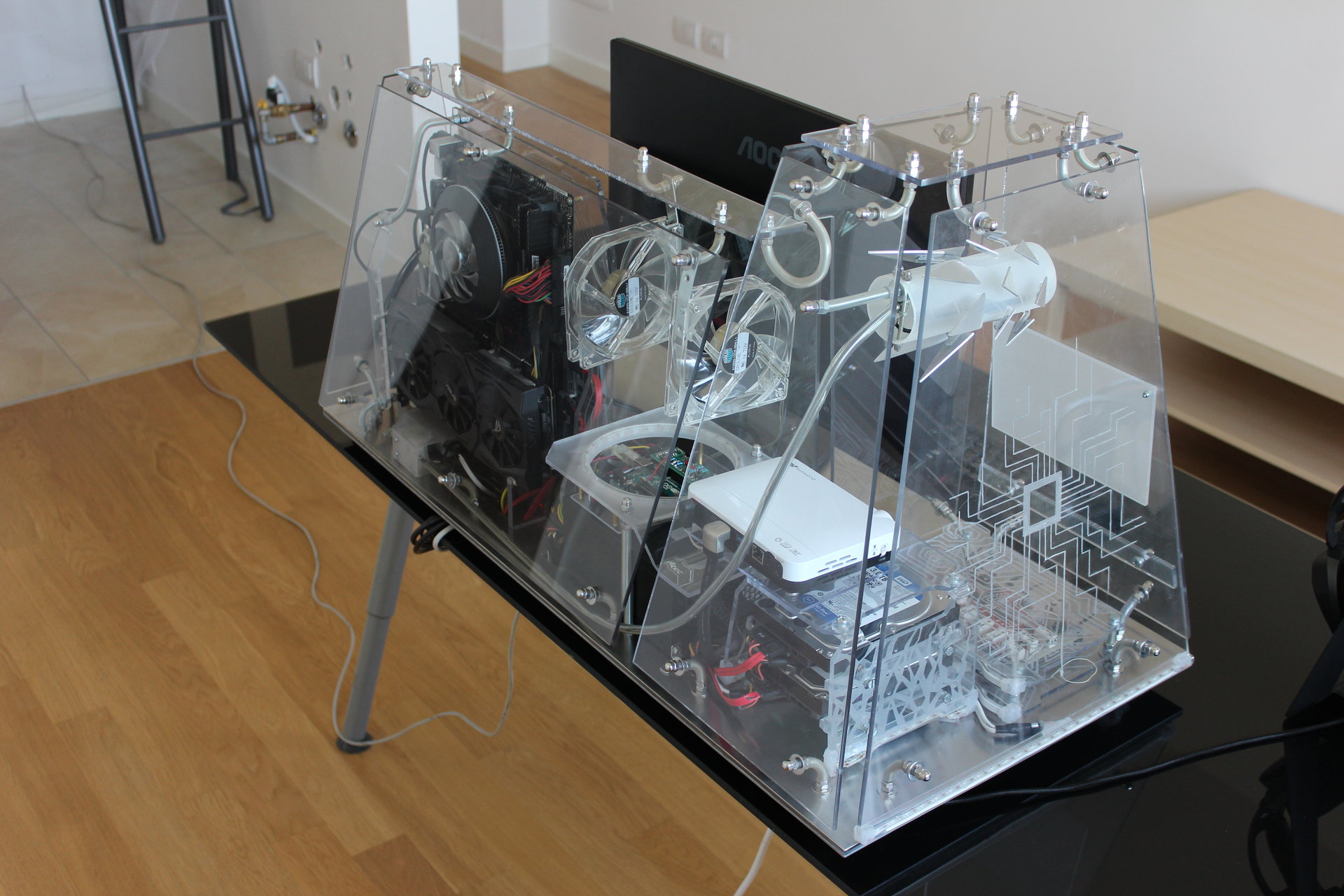
And now it has finally arrived the moment to reassemble all the parts of the case!
Motherboard structure:
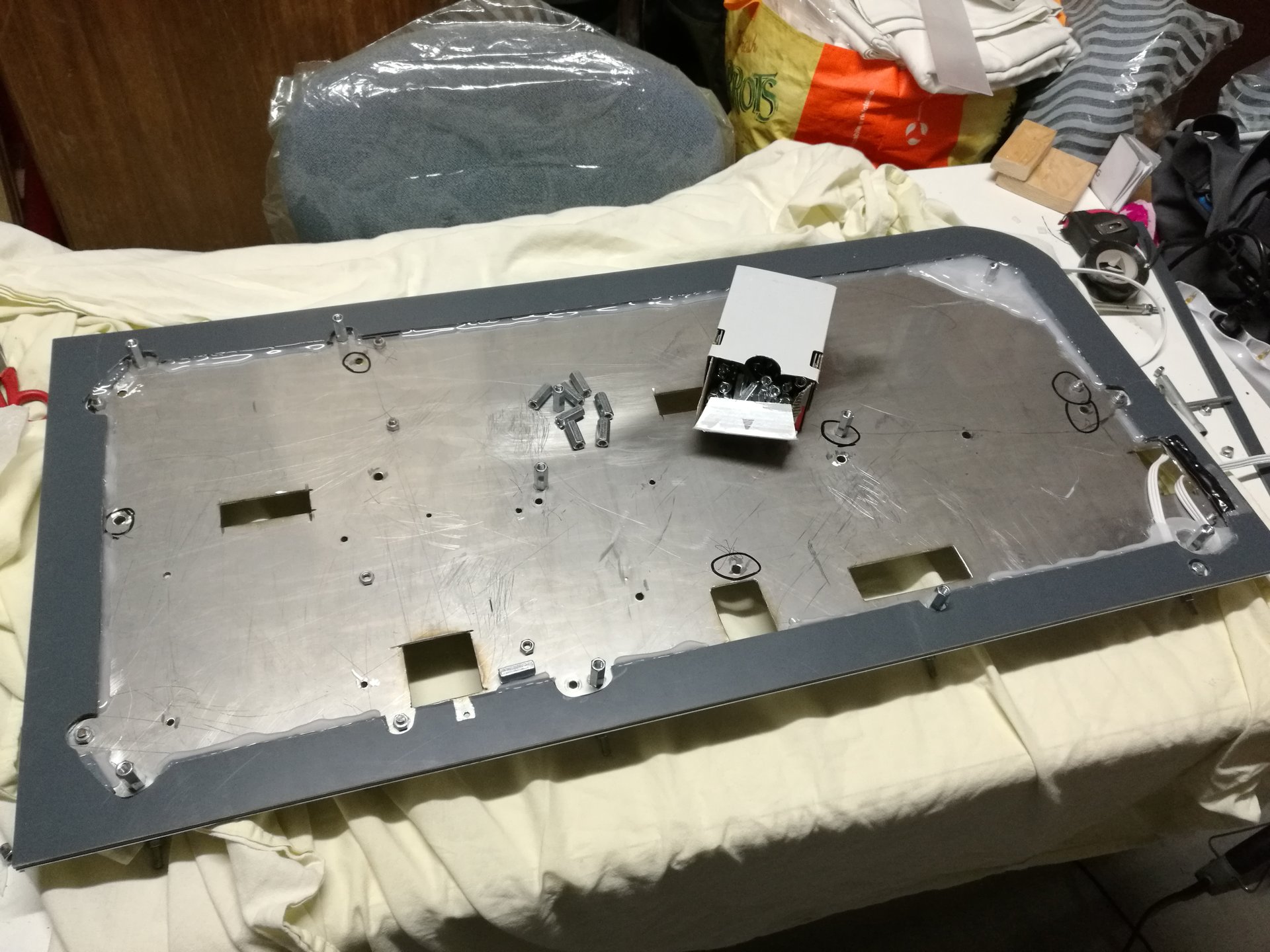
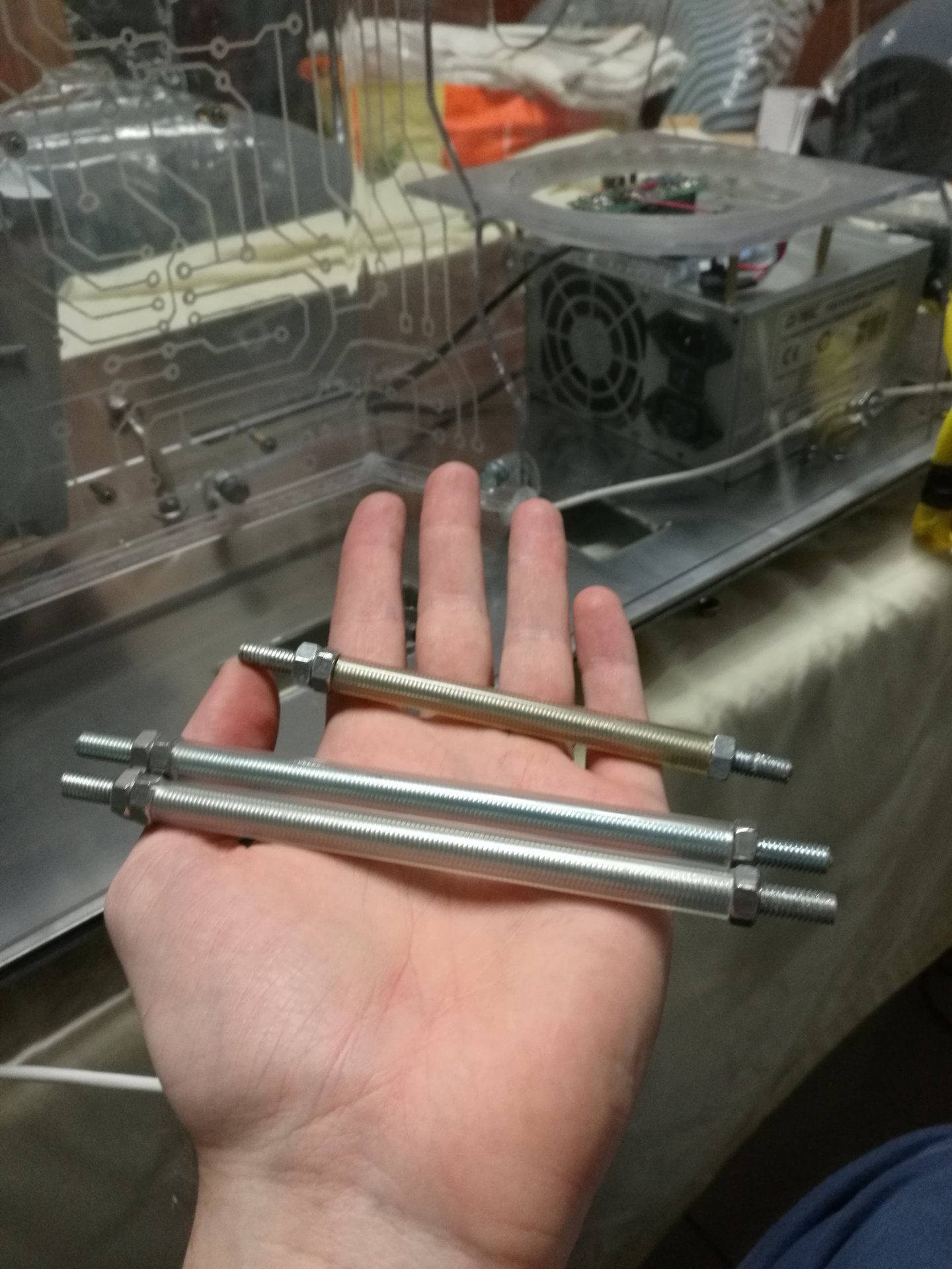
I have had to replace the two threaded bars of the PSU cover with two longer bars, because my current PSU is bigger than the old one, and also I needed some space for Arduino:
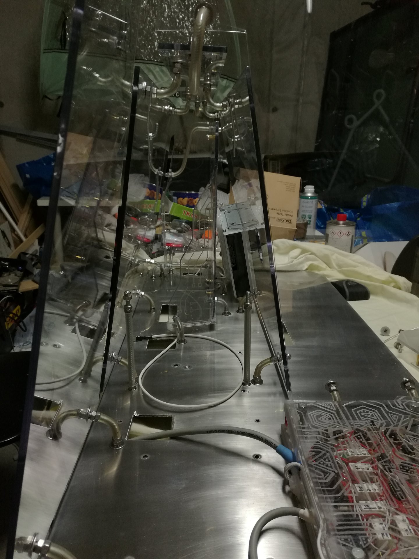
Then I mounted the sensor circuit encasing, the sensor bar, the feedback leds, the PSU cover and the optical drive (and I finished to replace all the nuts and washers with stainless steel ones):
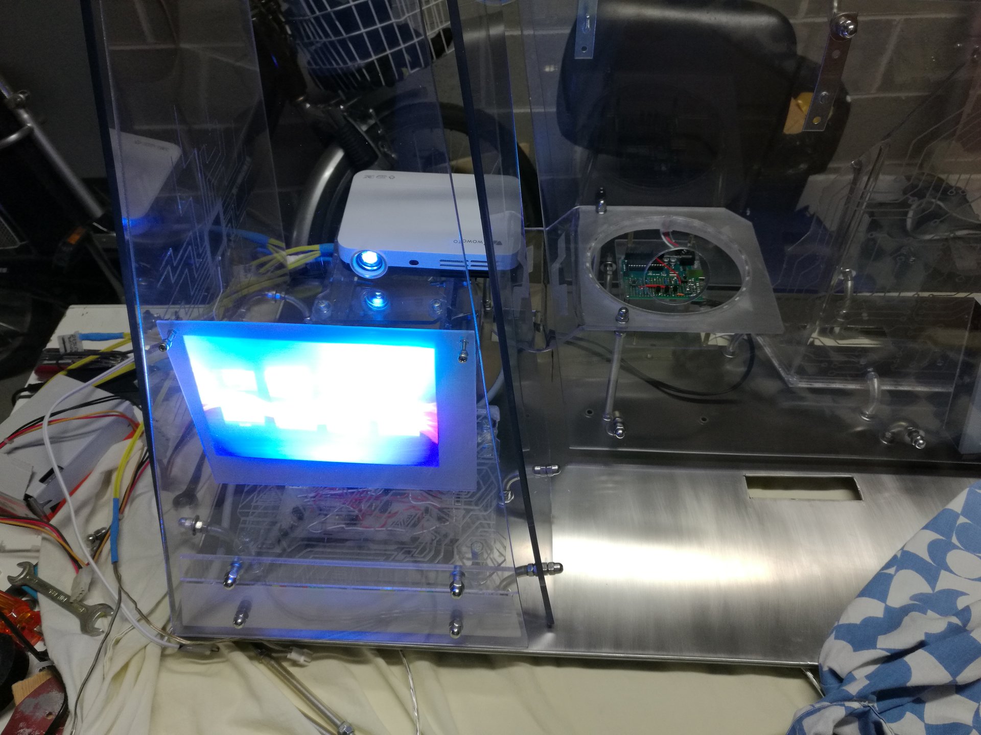
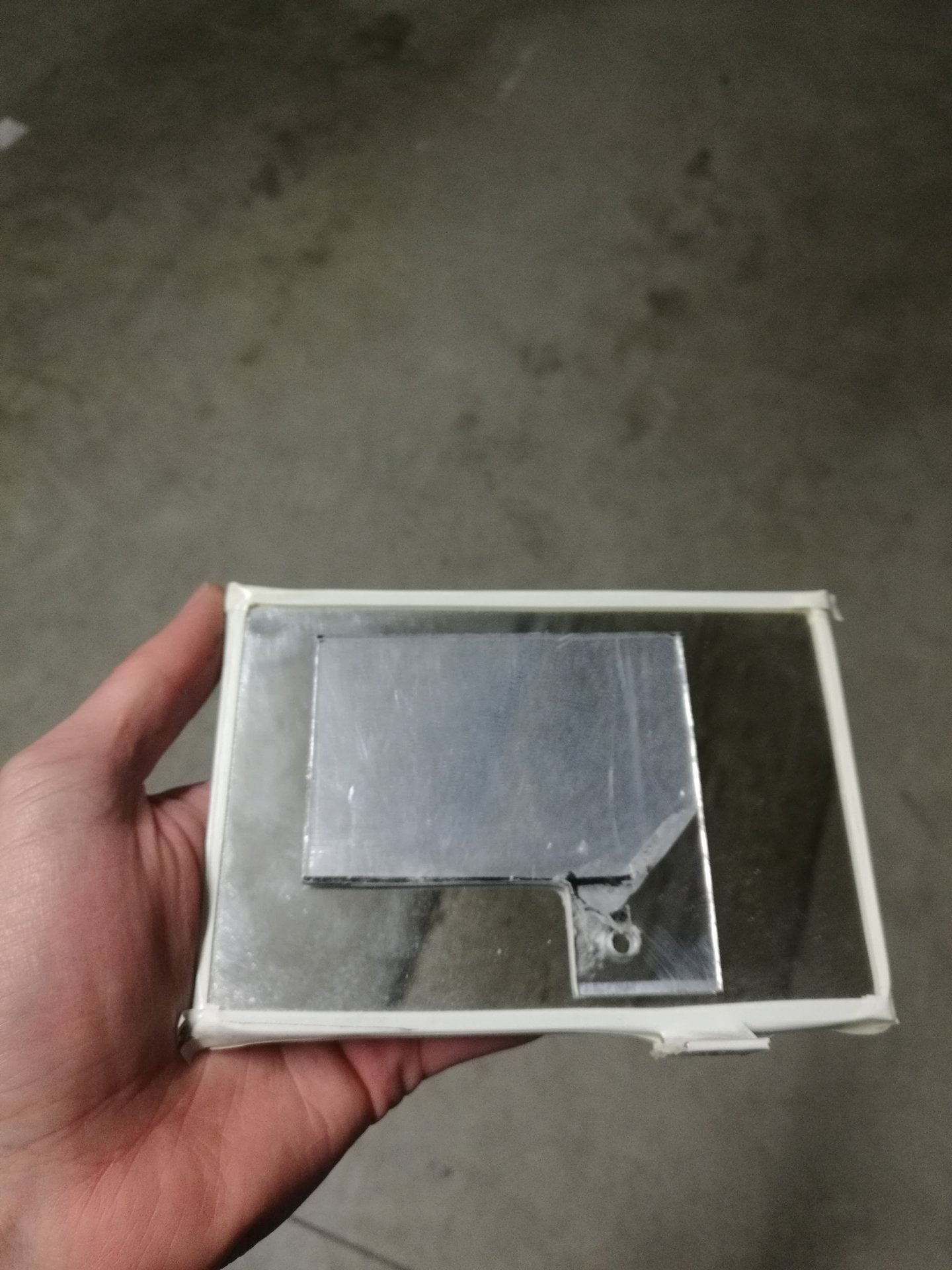
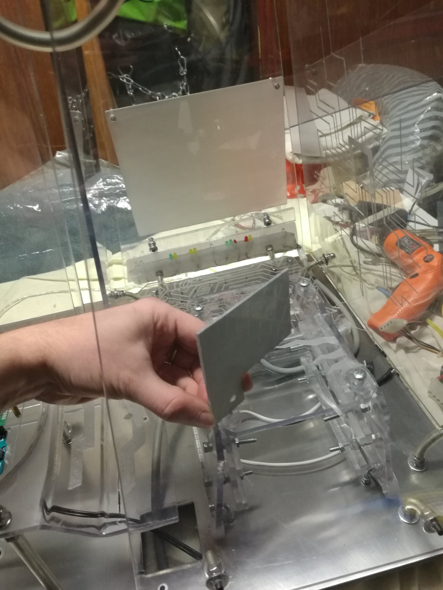
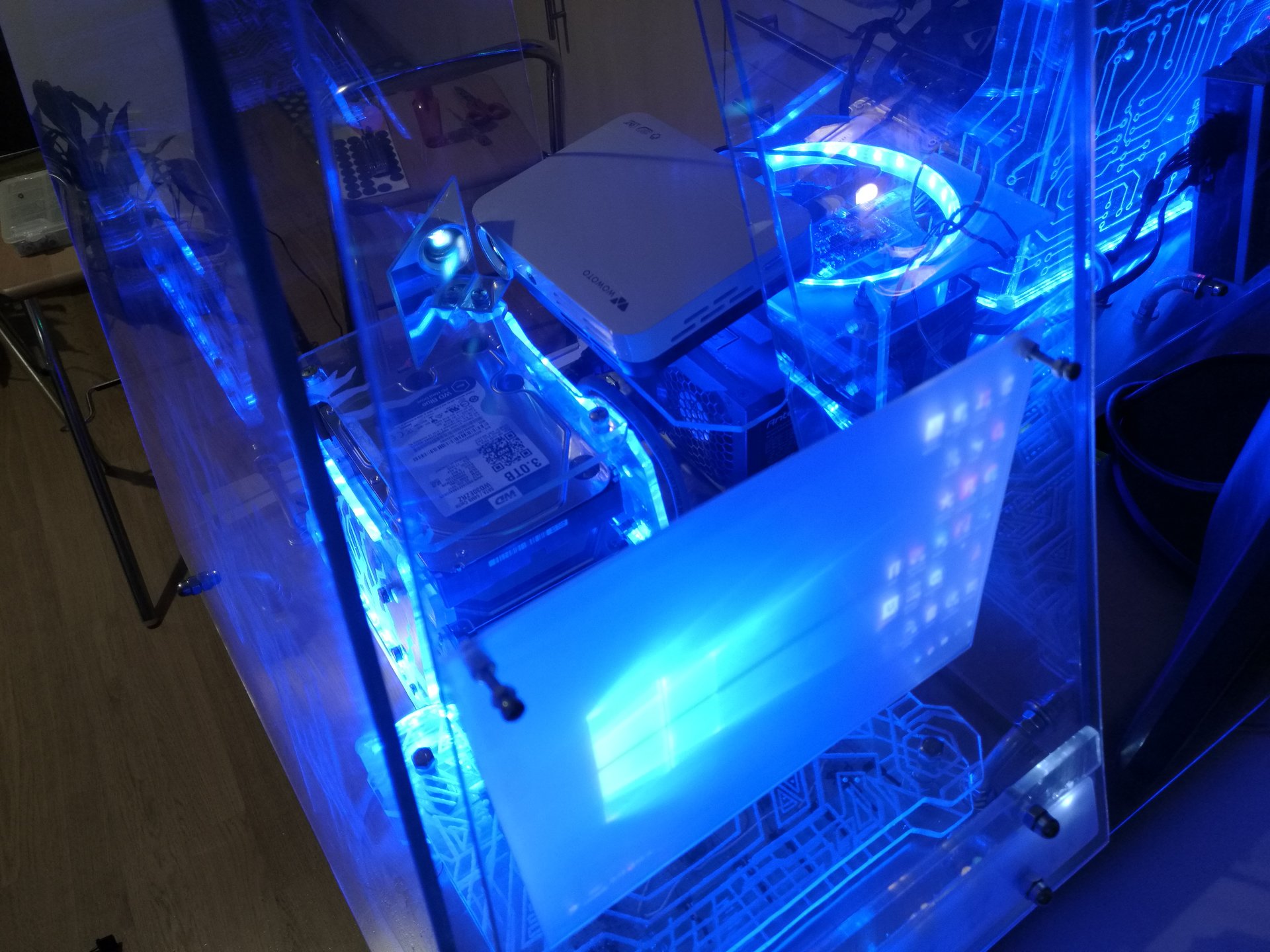
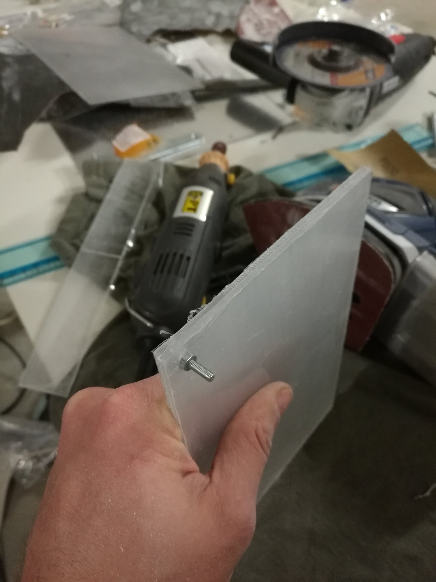
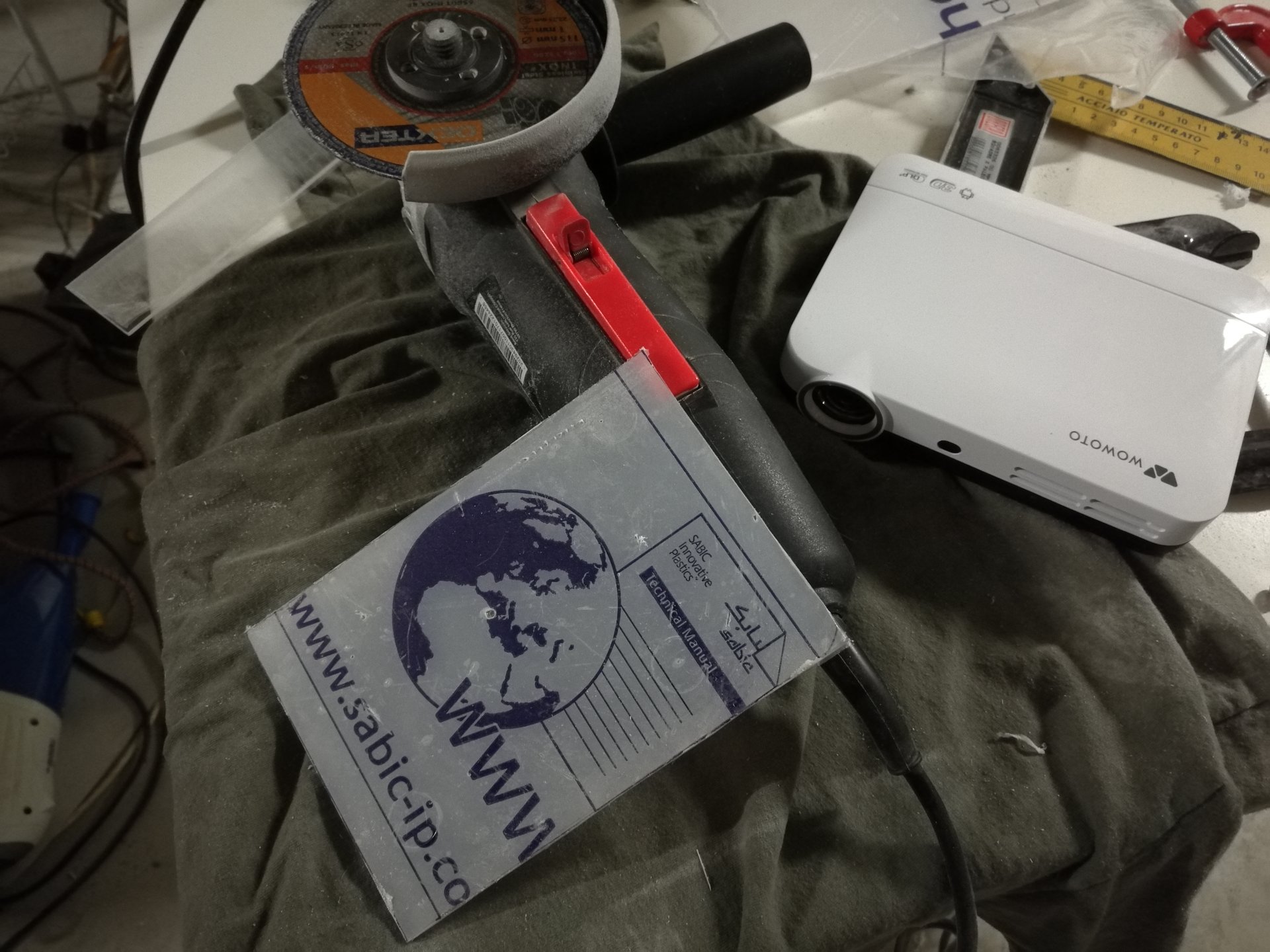
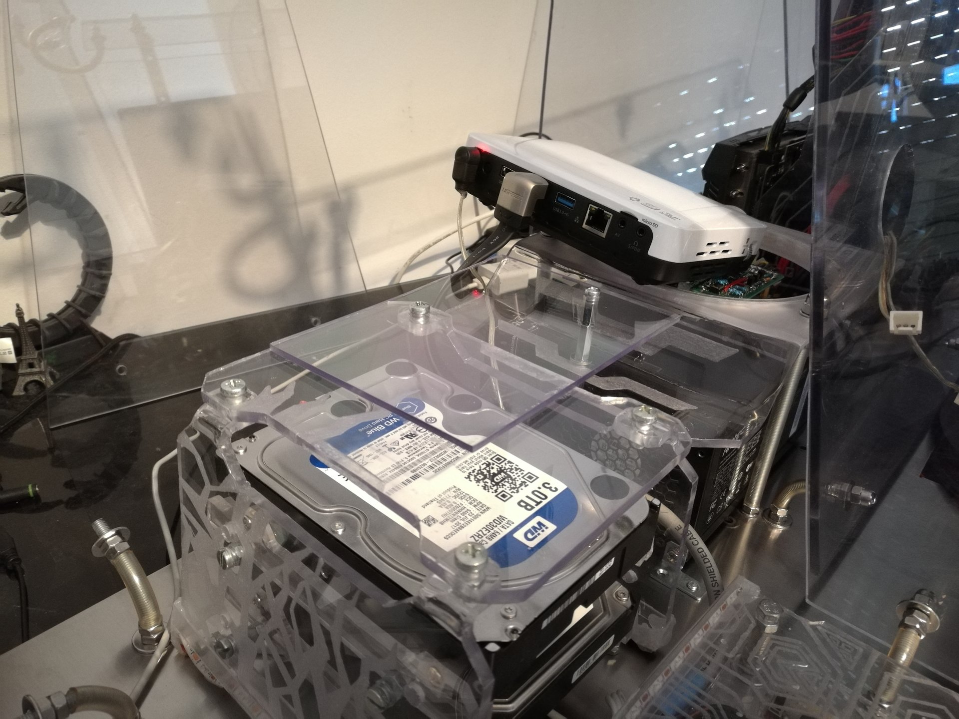
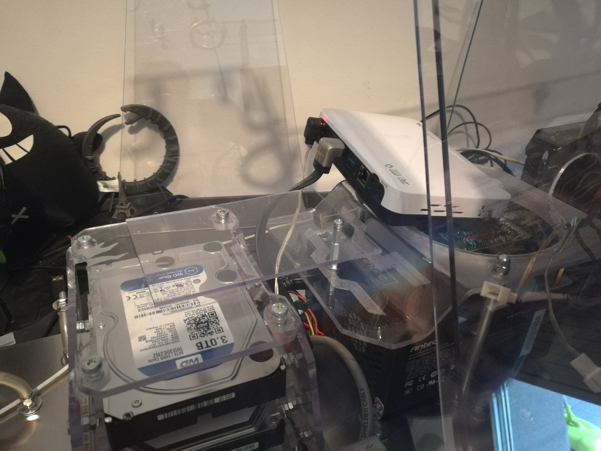
Then I have tested my new mini-projector (1280×800, more than enough for that screen size), and I replaced the projector’s mirror with a smaller one (made in plexiglas, so I’m been able to bend it with heat):
Note: I put these mirror pics in the project log only for documenting this work, but then I have removed the mirror because the new projector I’ve bought has a lot wider projection cone than the old one, so I put the projector directly behind the projection screen (above the hard disks)
Meanwhile I was working on the software too:
I have programmed a Java application (that I called KernelController 😀 ) for the PC, that communicates bidirectionally with Arduino using the serial port.
The application has these functions:
– it can query Arduino to get the list of the lighting states that I have programmed (including some monochromatic, polychromatic, animated and mixed states)
– it can select the desired lighting state from the list
– it shows the current selected state (even if it is selected directly by the proximity or touch sensors)
– it launches an appropriate animation on the projector, when some lighting state is selected. For example it launches a red alarm signal animation when selecting the pulsing red state (this function can be disabled, because it can be annoying in some moments)
In these videos I’m testing some functions of the application: changing lighting states and starting animations on the projector:
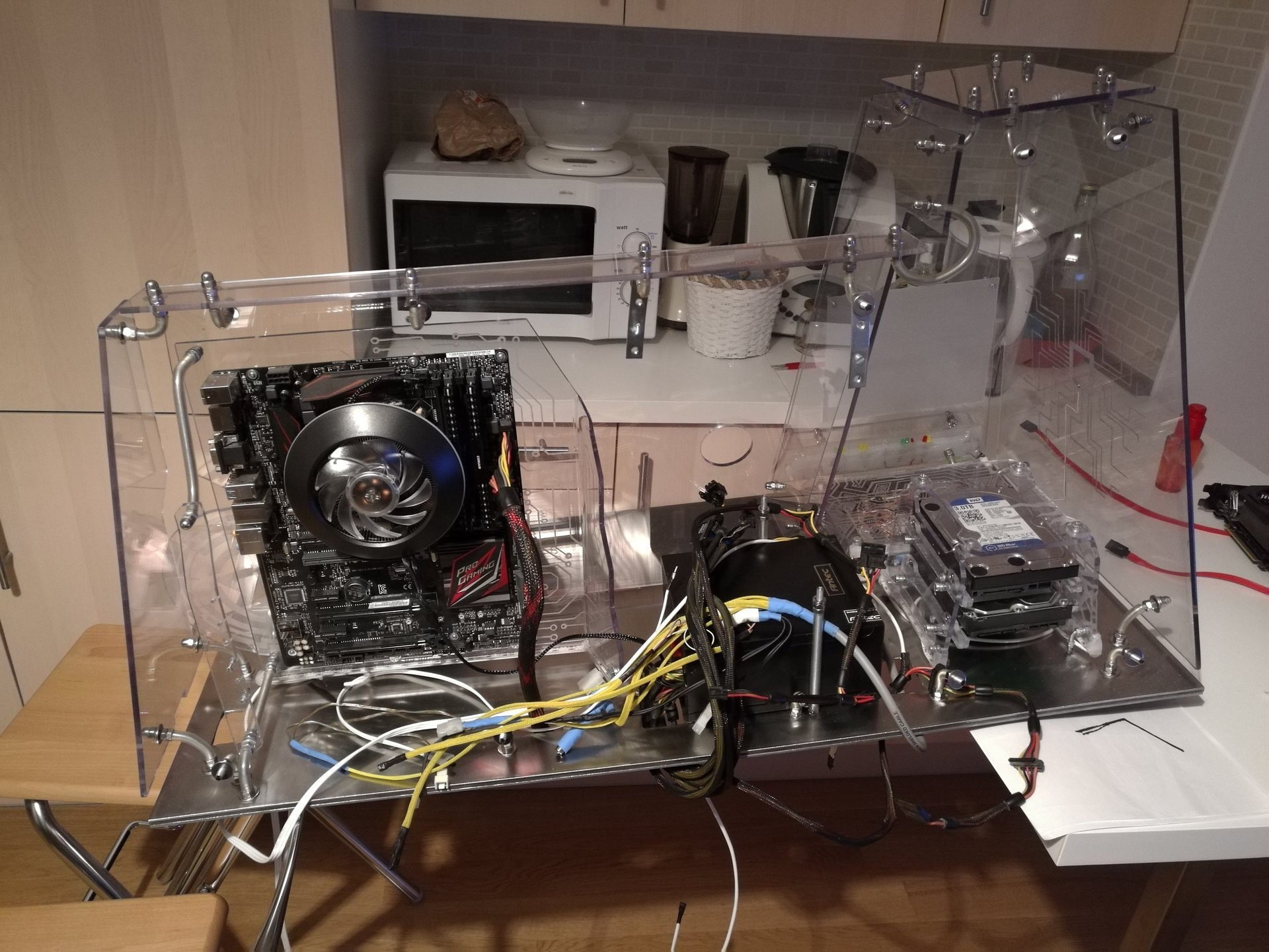
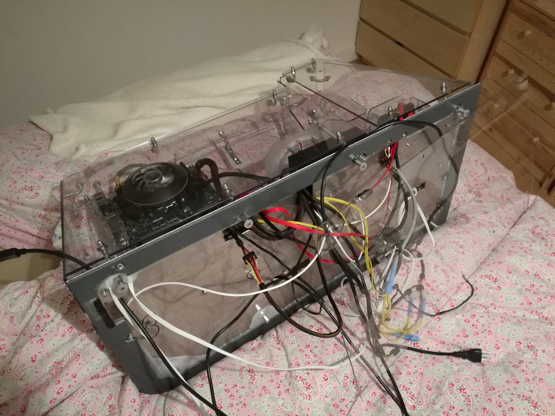
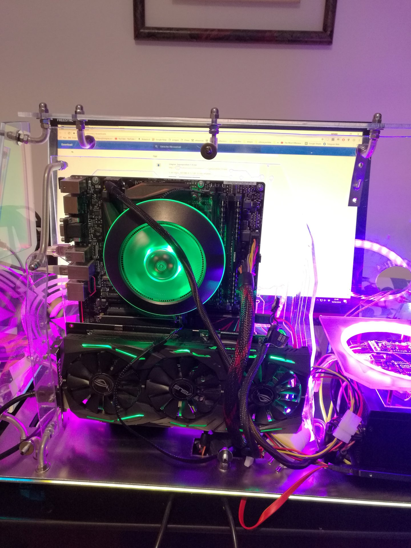
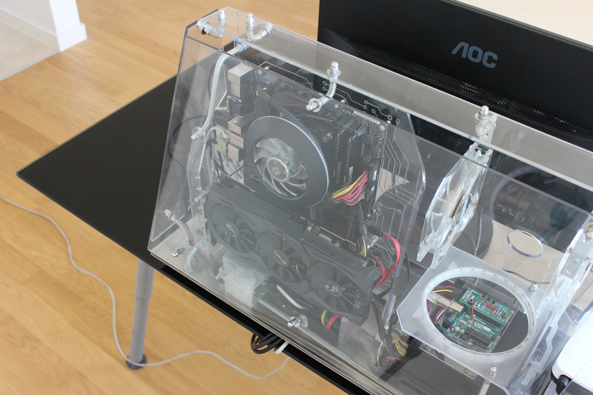
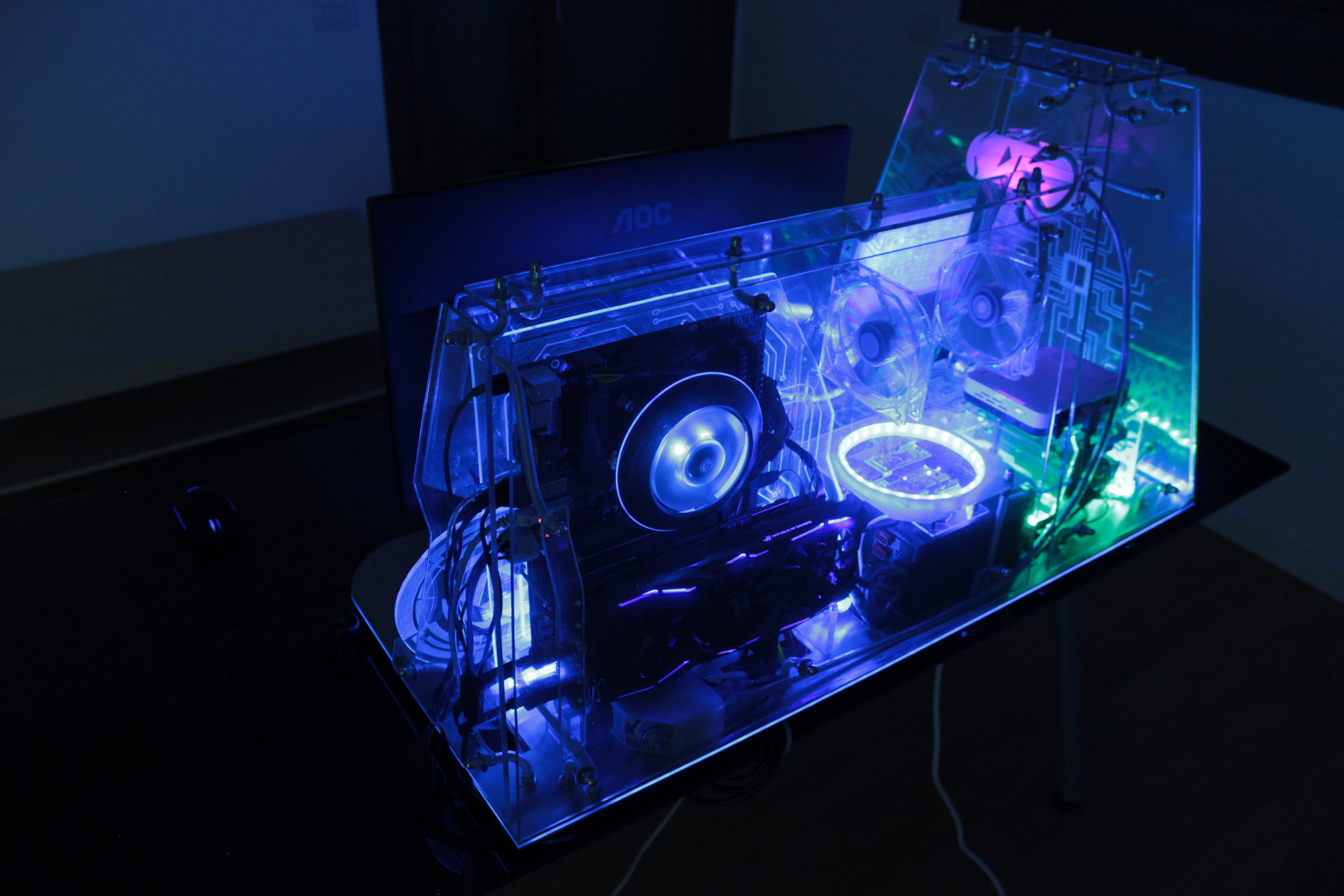
And now it’s arrived the moment to assemble the PC!
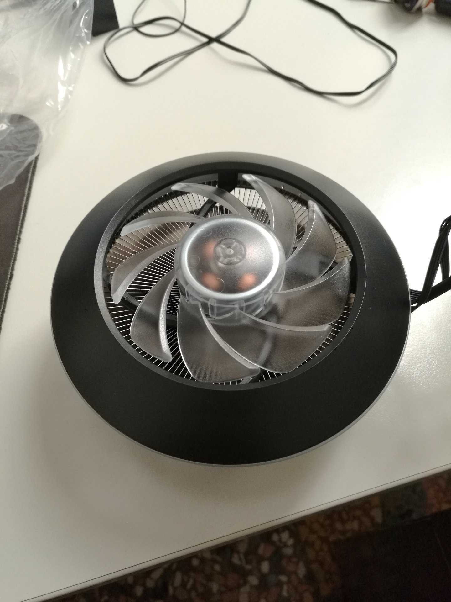
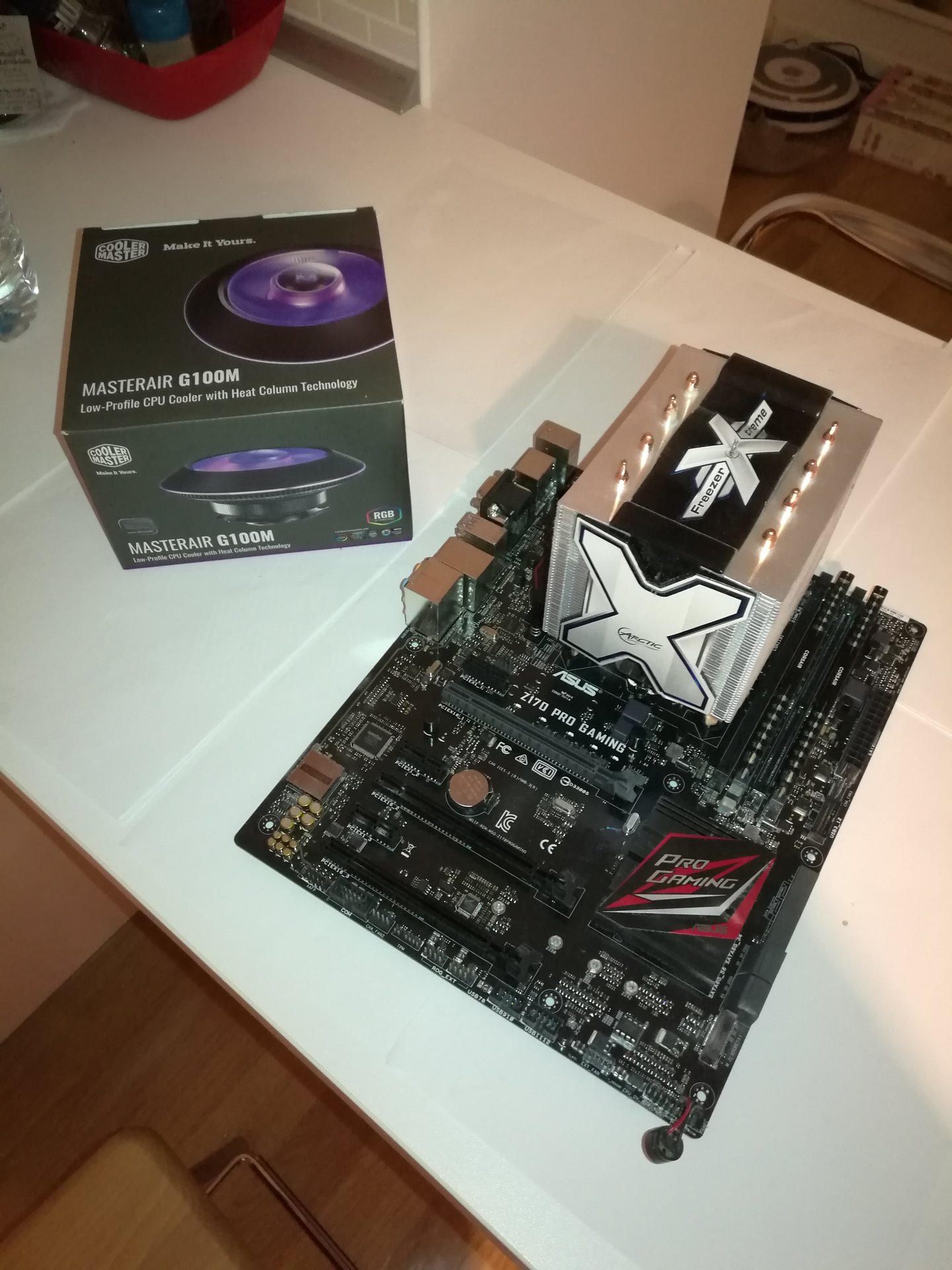
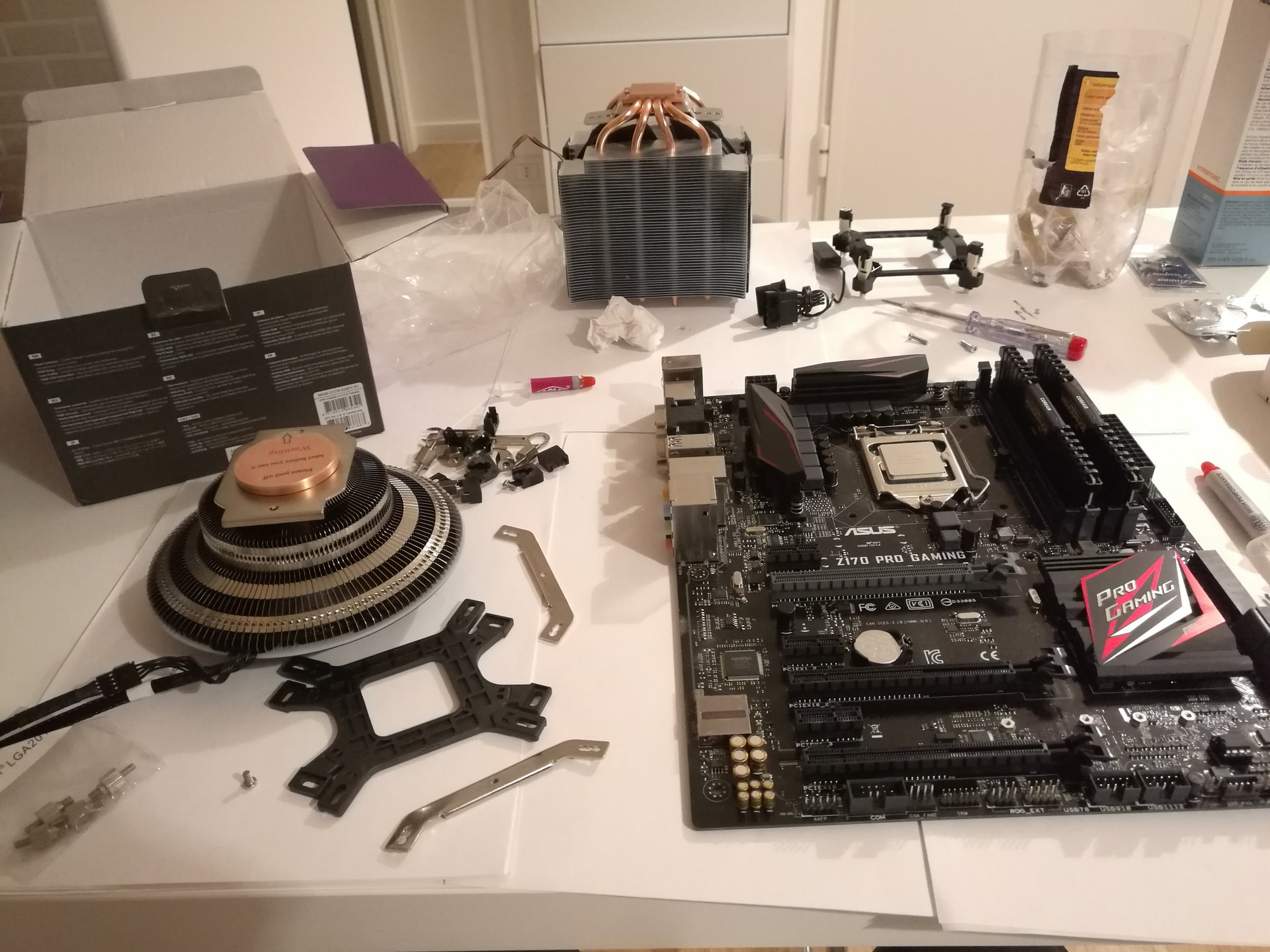
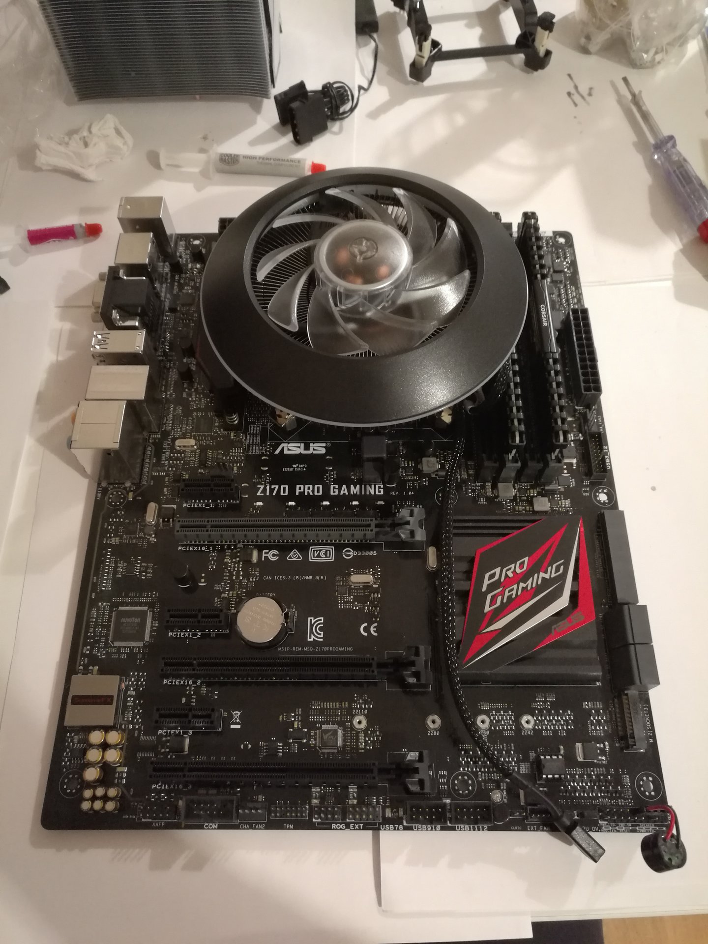
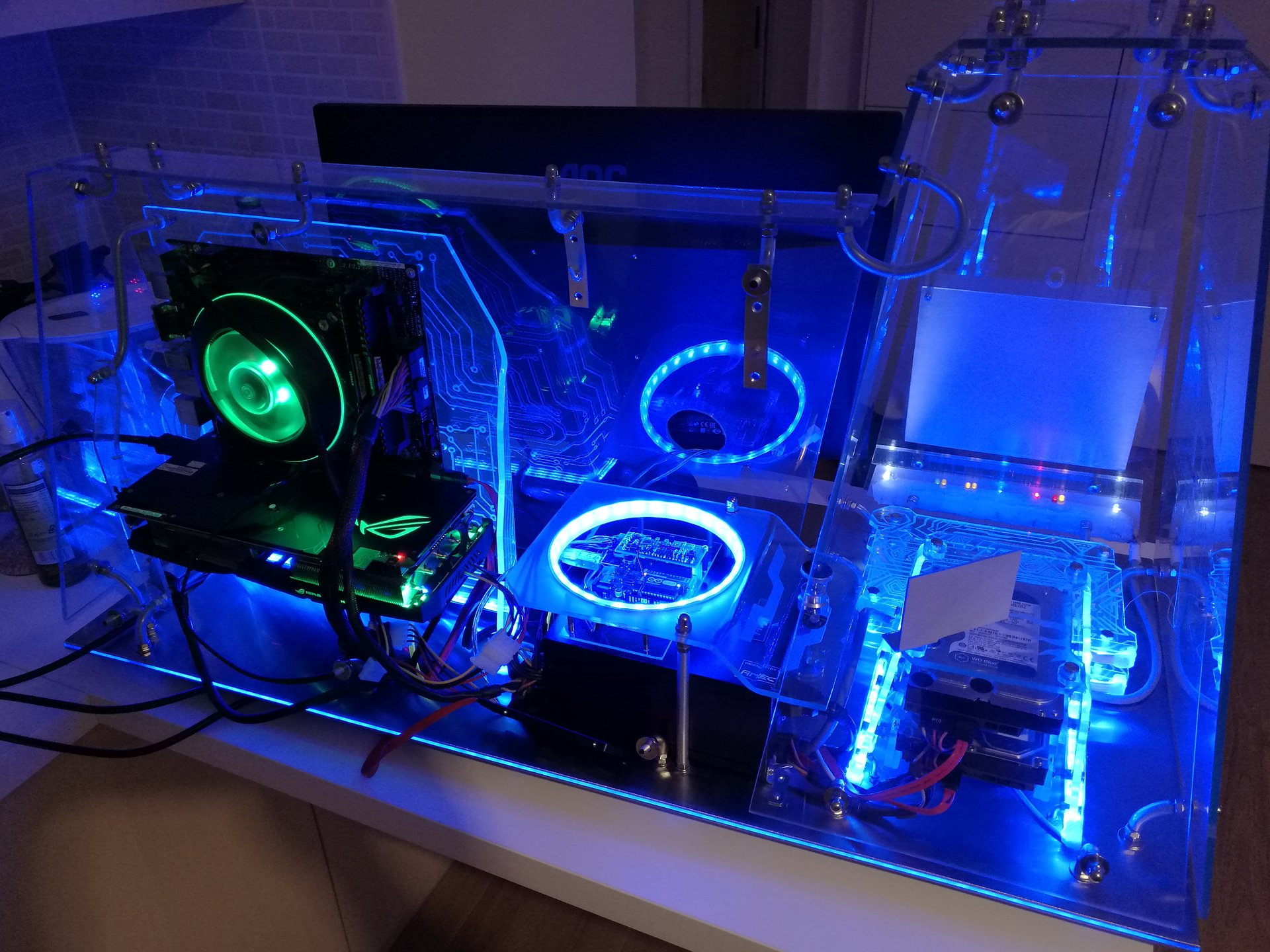
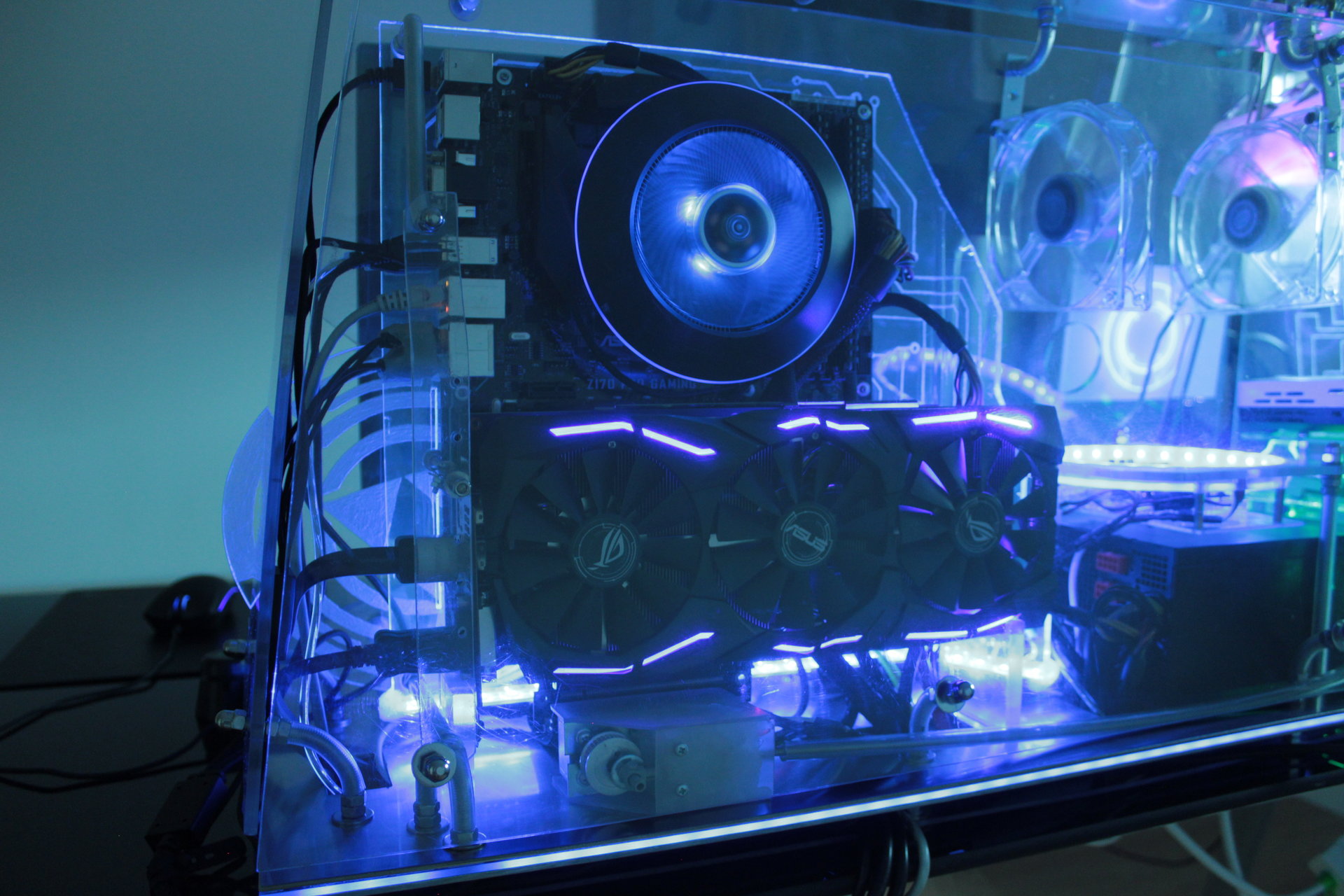
First, I replace my CPU heatsink with a Coolermaster G100M, because… well, should I explain it? 😀 😀 😀
Here I’m replacing the heatsink:
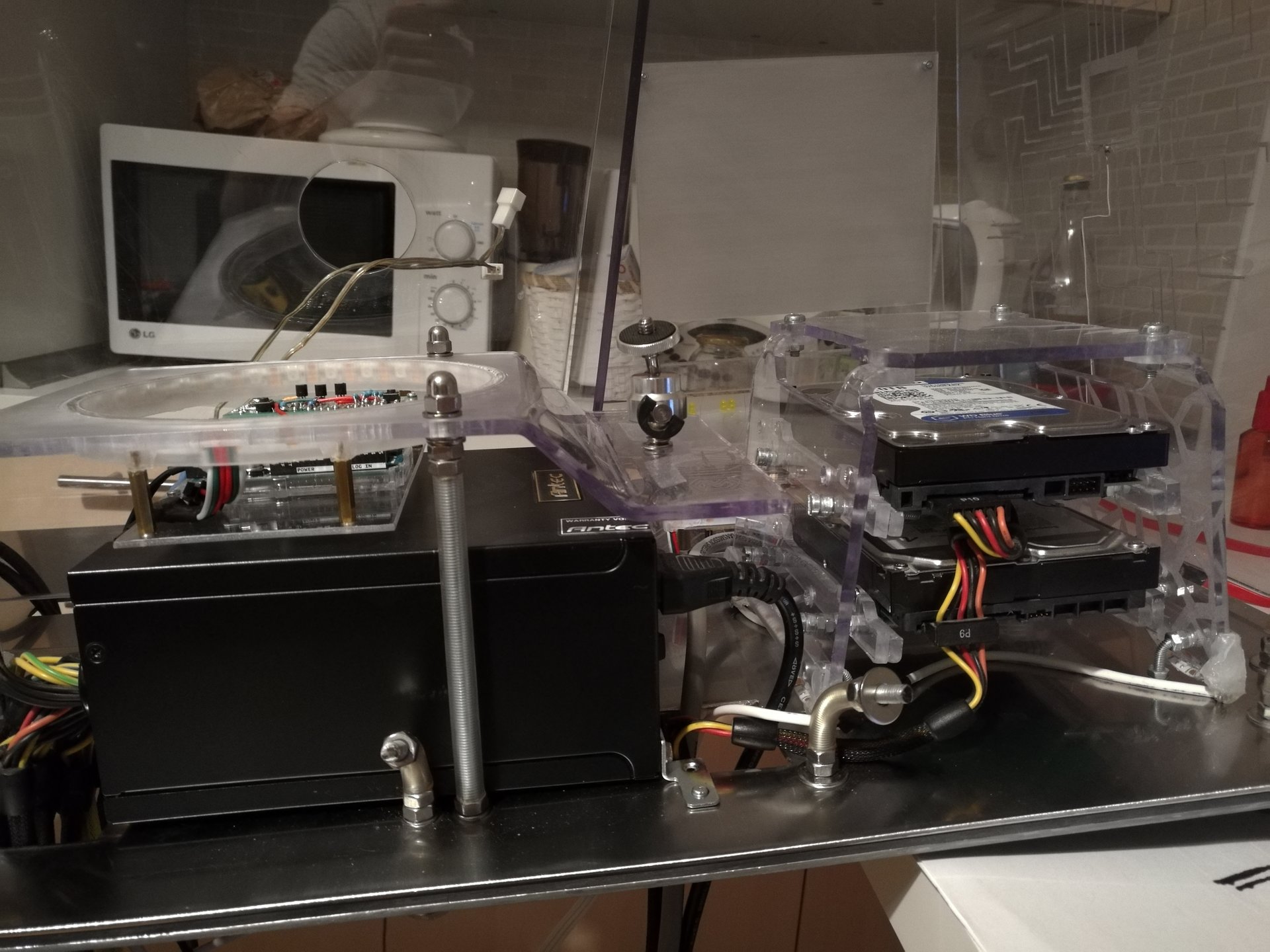
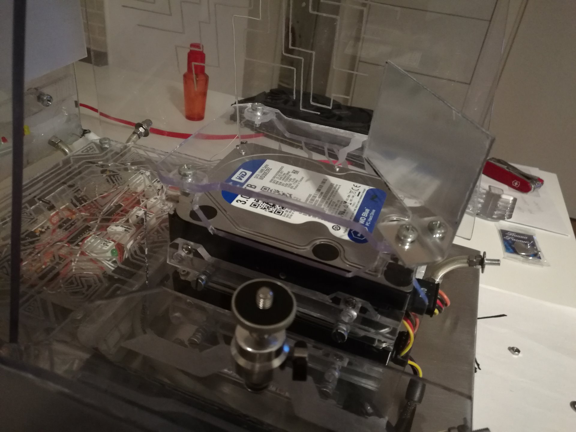
Then I start to assemble the hardware, passing all the cables under the base through it’s holes:
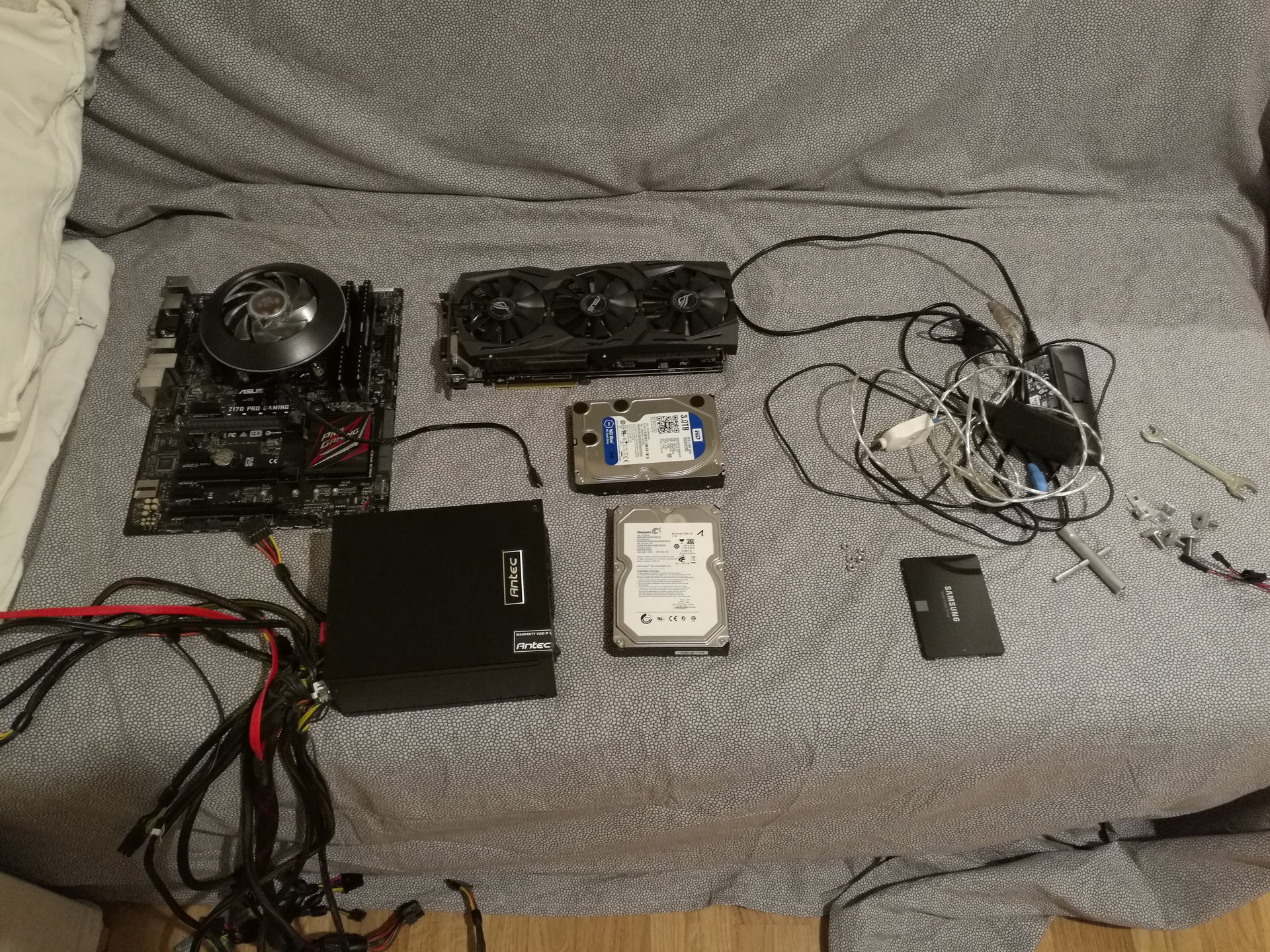
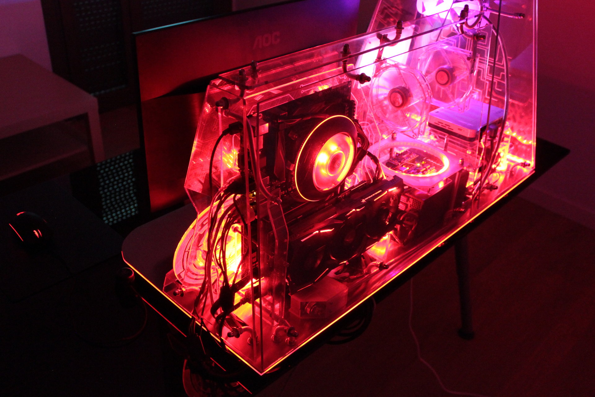
(the hardware is: Corei5 6600k, Asus RX 580 8GB, 16 GB RAM, motherboard Asus Z170 Pro-gaming, 1 SSD and 2 HDD, PSU Antec Signature 850W)
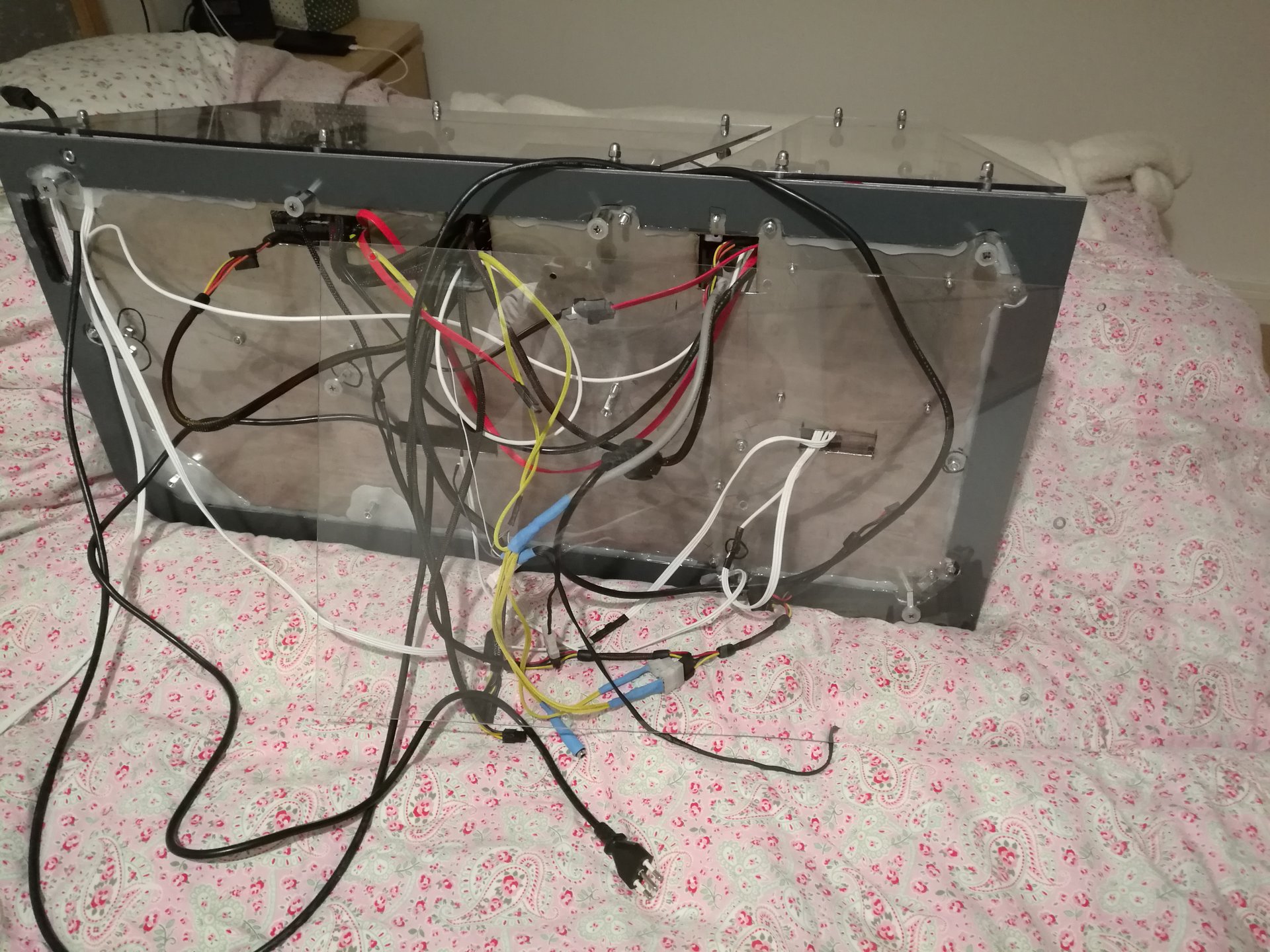
Then I mounted the transparent bottom panel of the interspace below the base (here we can see all the cables that I have hidden under the base):
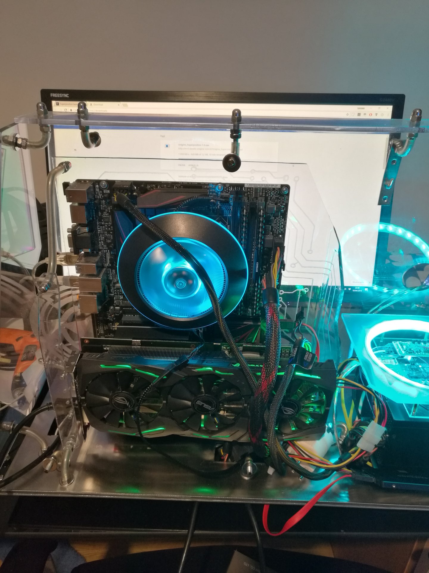
And now I try turning on the assembled PC for the first time:
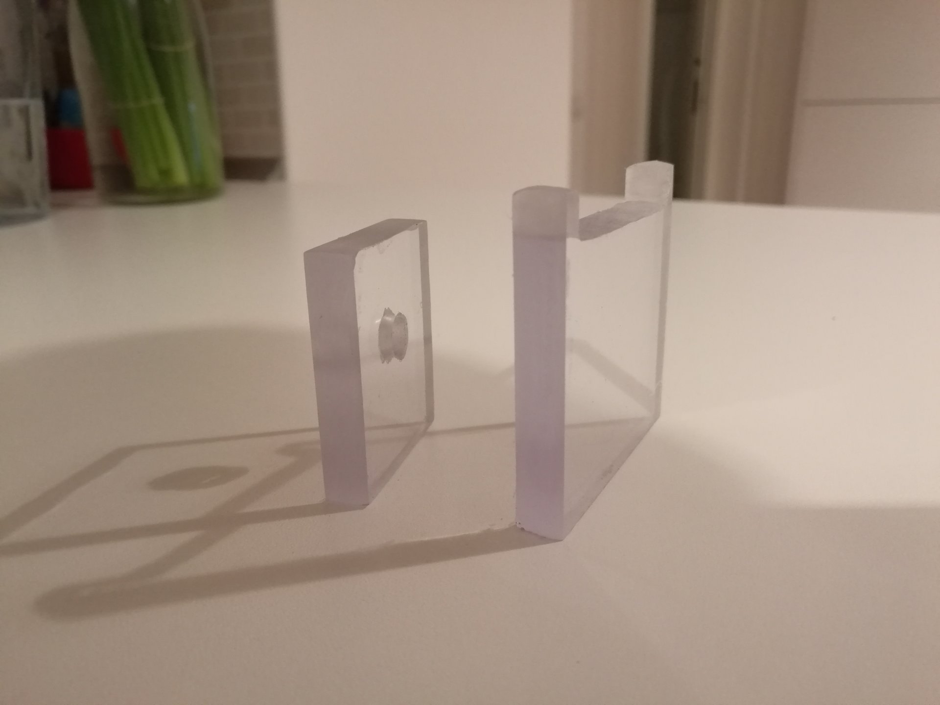
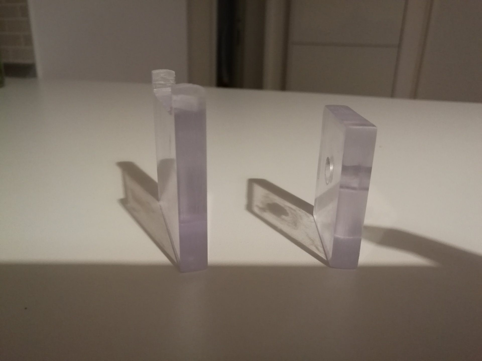
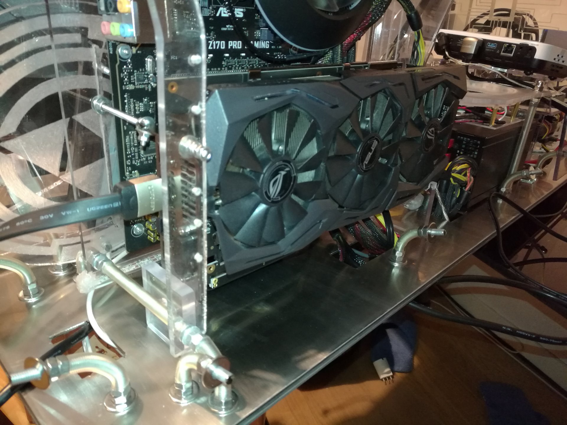
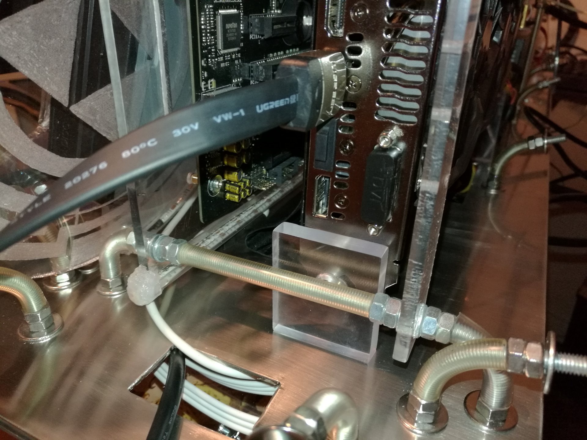
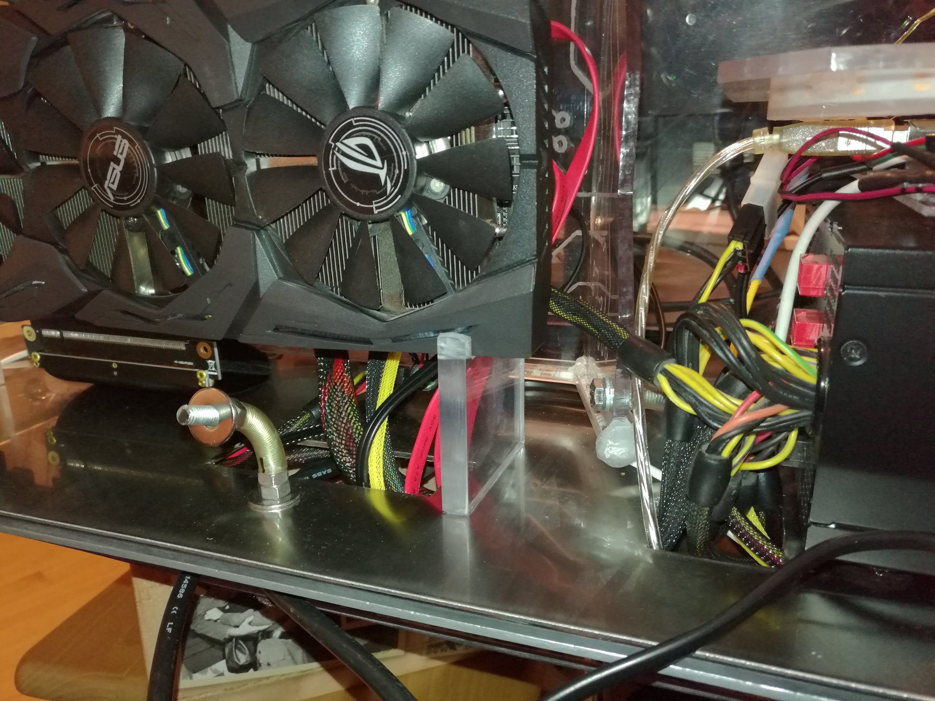
Then I have mounted the video card vertically, connecting it with a 25cm riser cable, and I have made two transparent stands from a thick panel of polycarbonate, to keep it still in position.
I also have hidden almost all the cables going to the motherboard behind the video card.
And then I modified radically another thing that I didn’t like of my old mod: the feedback led bar!
That bar was too ugly to keep it in foreground in the most visible part of the case, and also covers the engraved encasing behind, so I decided to move it in the same position, but under the base. In this way, the leds are still associated to the touch sensors over them, but now the bar is less visible. Also the front part of the case is cleaner and it shows a lot better the engraved panels inside.
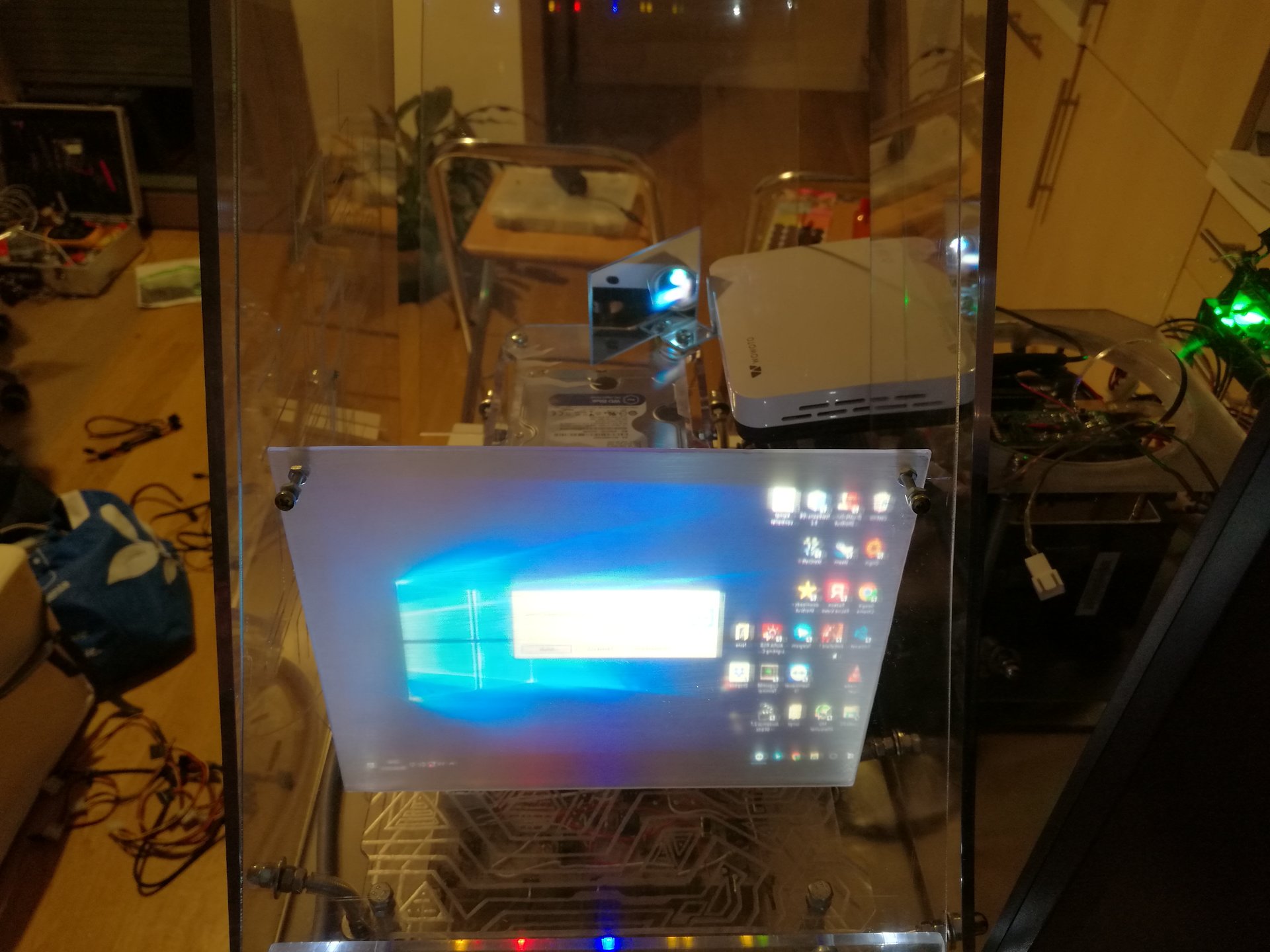
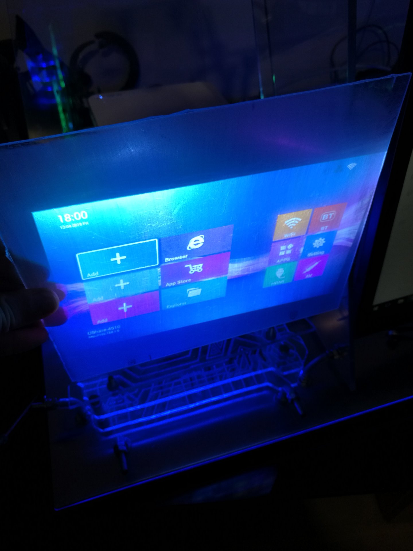
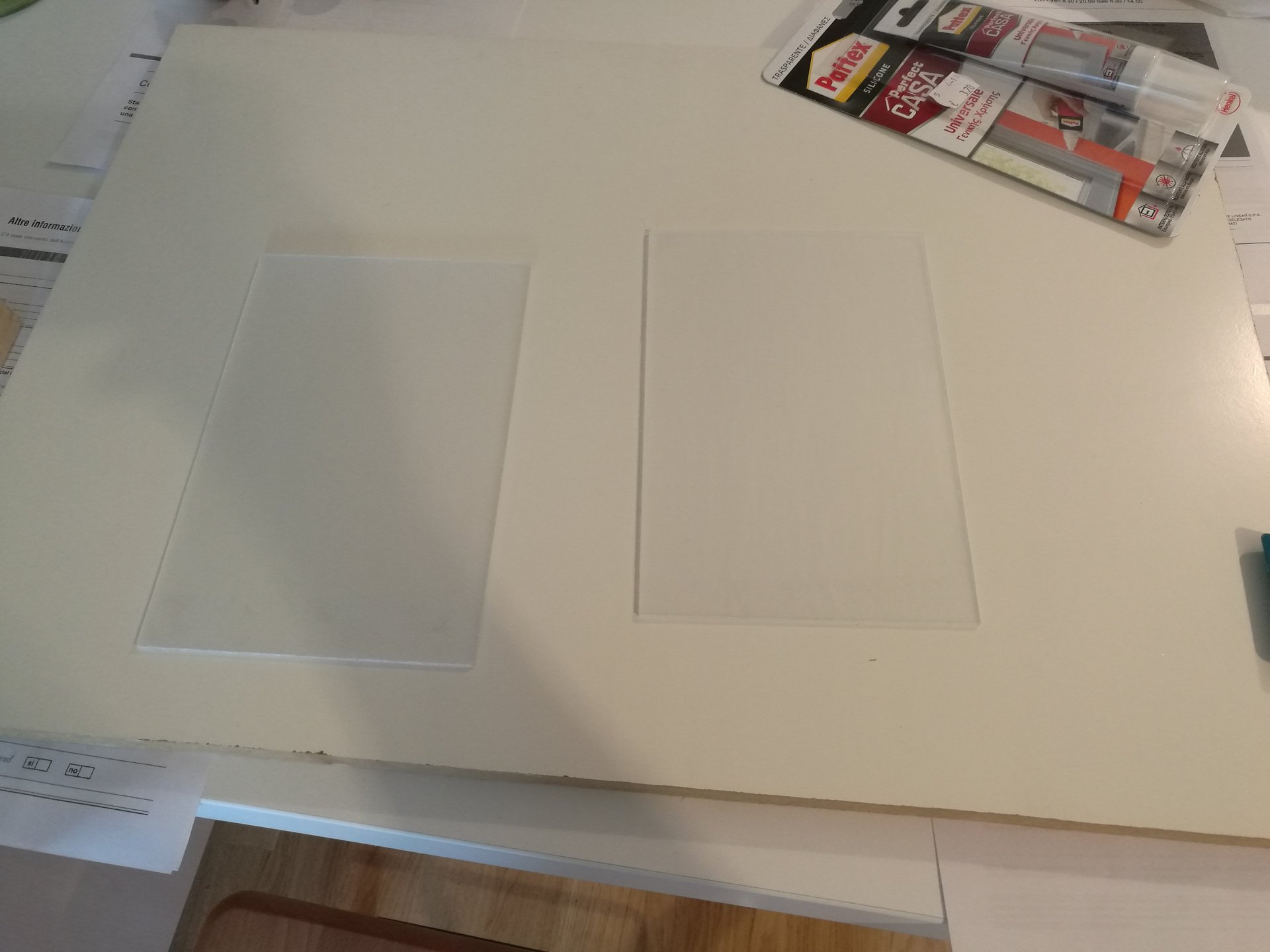
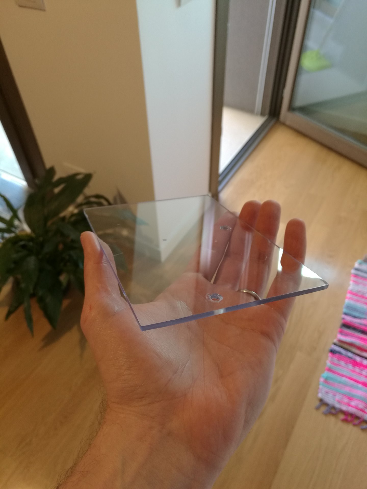
I replaced the old projection screen (4:3) with a 16:10 projection screen (the new projector’s ratio is 16:10, 1280*800).
Here I had to solve a problem: sanding two faces of the panel there was an annoying parallax effect, and sanding only one face the projection wasn’t bright enough.
So I solved the problem sanding two panels, each on only one face, and fixing them together with the sanded faces in contact. In this way, the sanded faces are two (brighter projection), but they haven’t a gap between them (so no parallax).
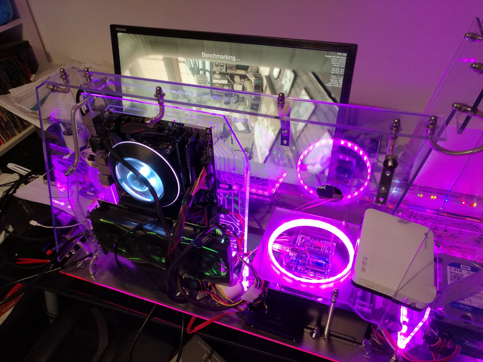
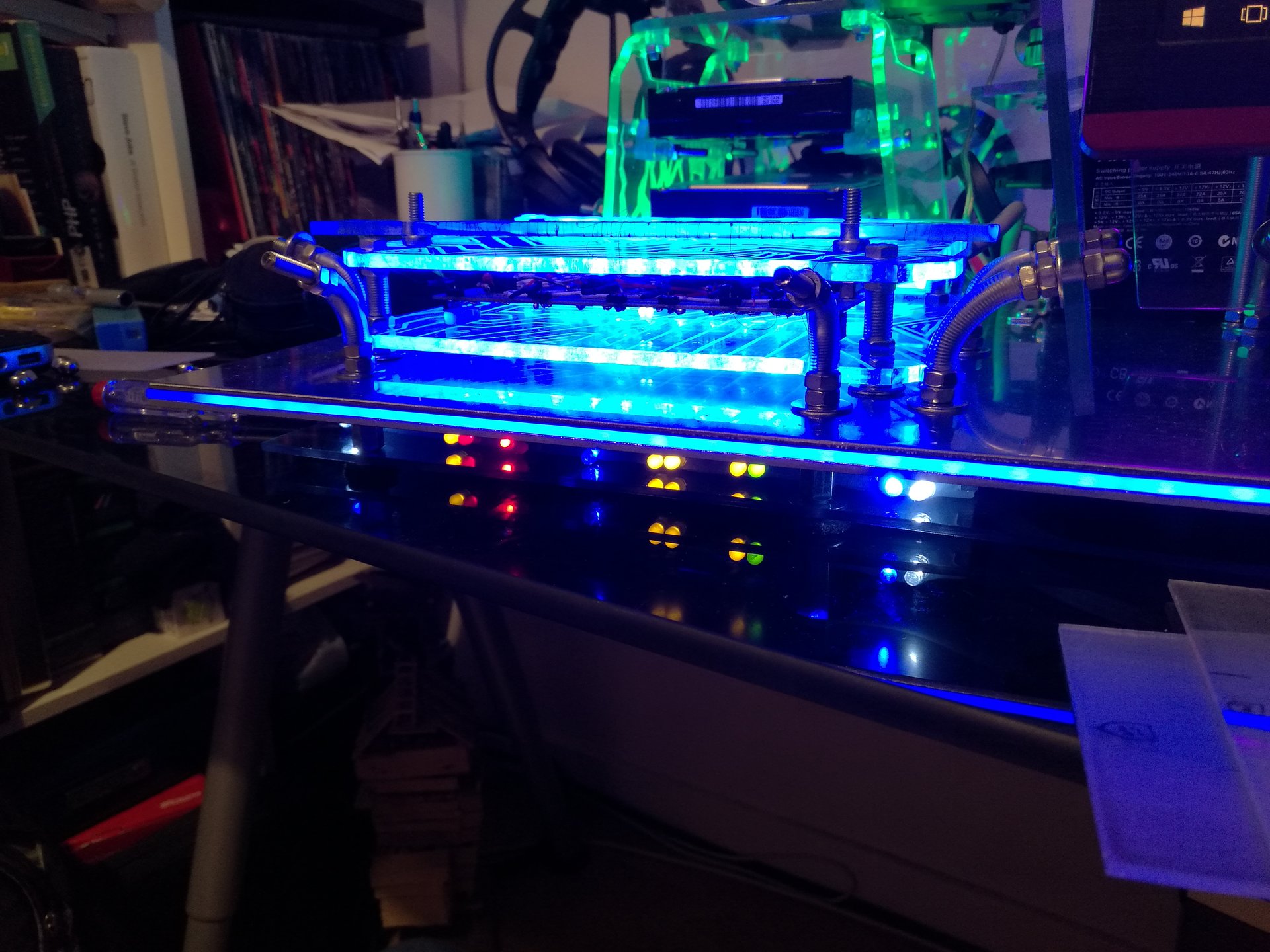
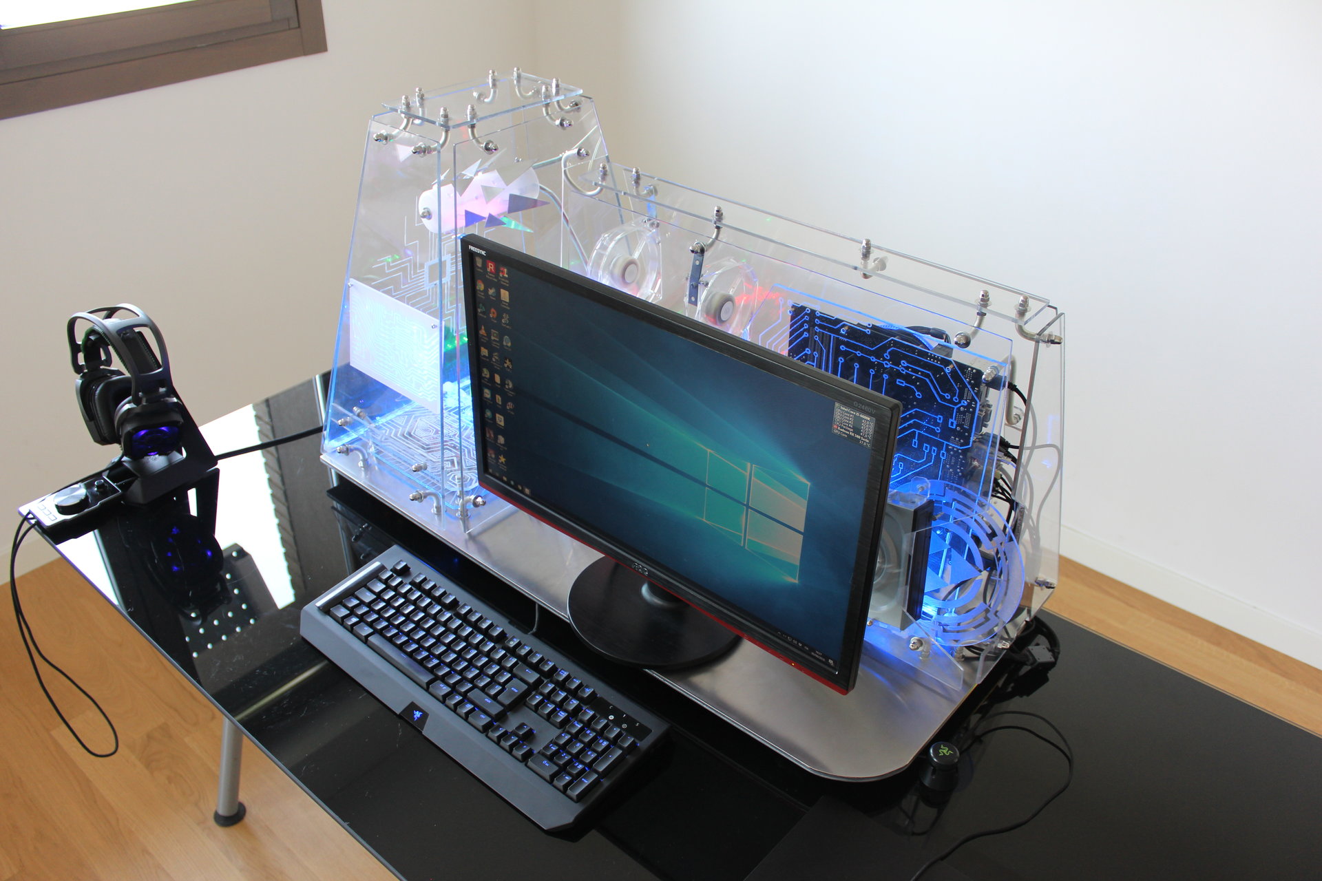
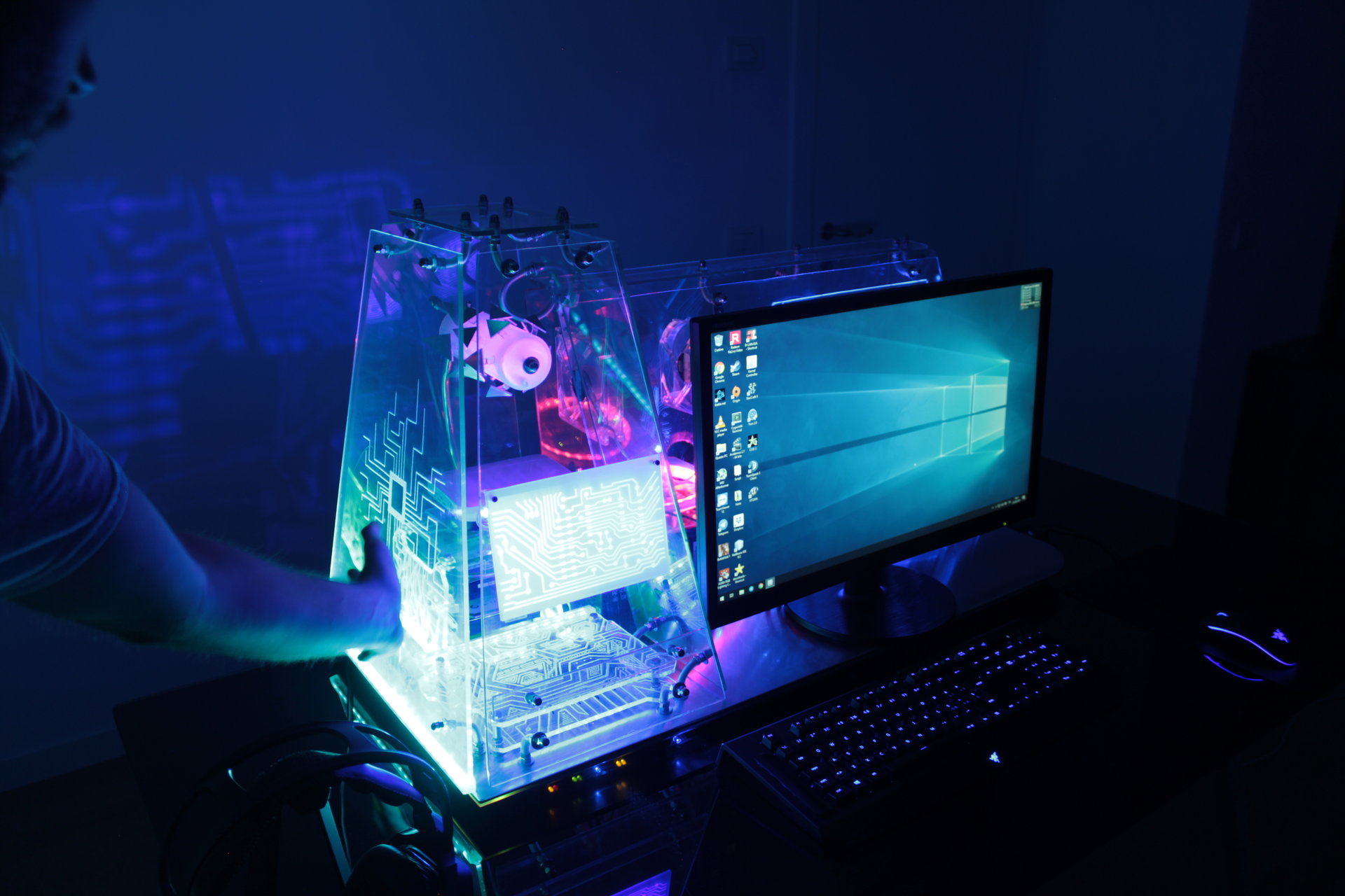
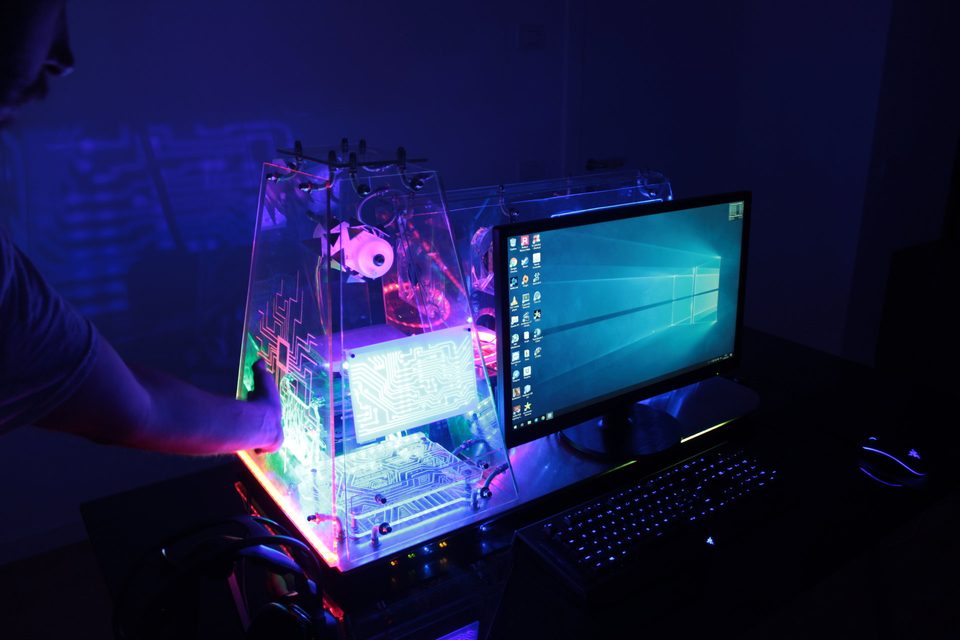
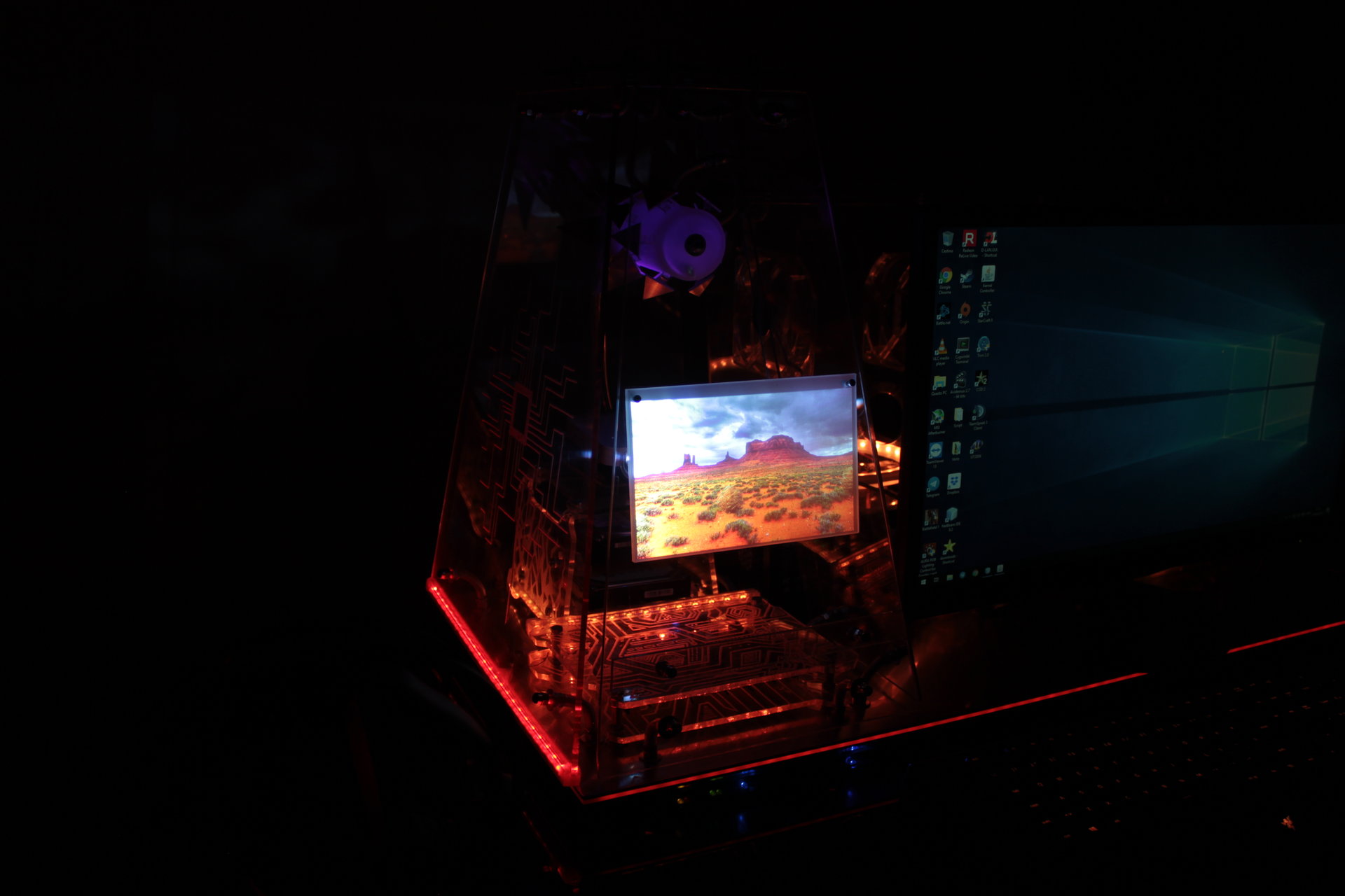
And this is the result (the projection is too bright for the pics, but seen live I can say that the projected image is clearly visibile and not blurry at all):
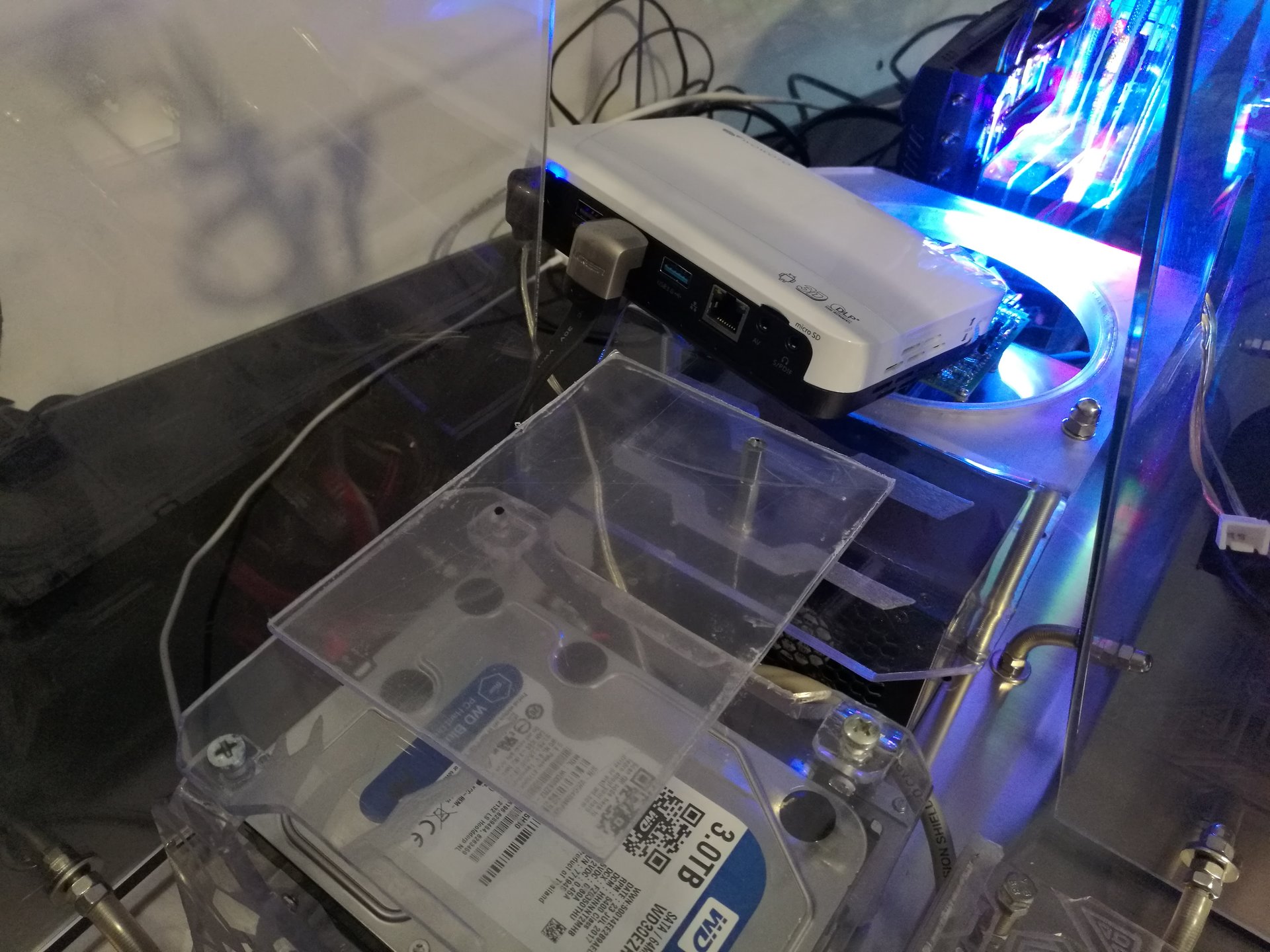
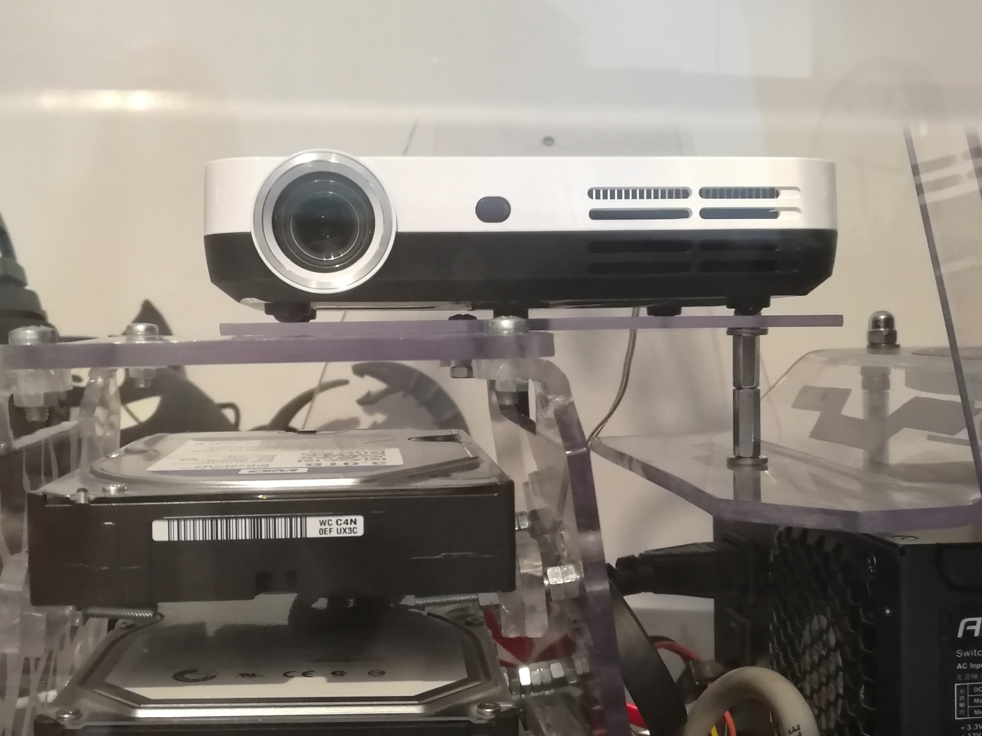
As I said before, I decided to remove the mirror and put the projector directly behind the screen, because even the mirror’s surface caused a parallax effect!
So I have made a polycarbonate “shelf” for the projector, to be mounted over the hard disks structure and the PSU cover:
Then I still had to mount a led strip: the one that lights the proximity sensor’s engraving.
This strip is particularly important, because it reacts to the proximity sensor events, giving some feedback to the user! 😀 (there are some videos of this effect below):
I have mounted the Prankster bit and his motor:
And I have inserted all the remaining cables inside the interspace below the base, in which I have also inserted the projector’s power supply and a hidden knob that changes the Prankster bit’s movement speed.
Finally I have moved the projector to center the projected image in the screen, and I have made some holes in the projector’s shelf to keep it in the right position:
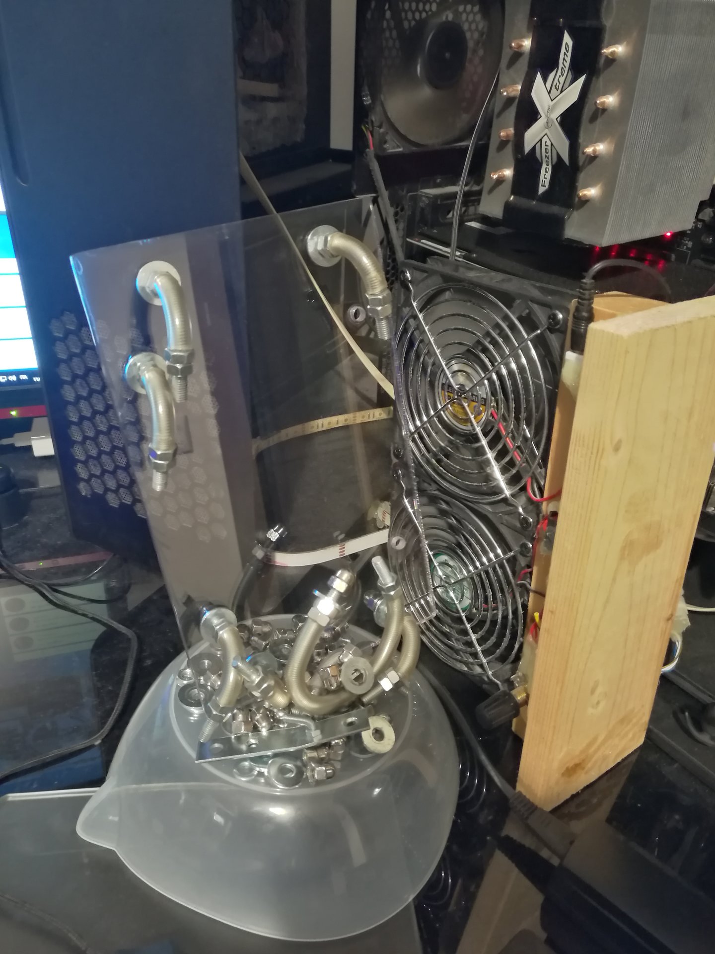
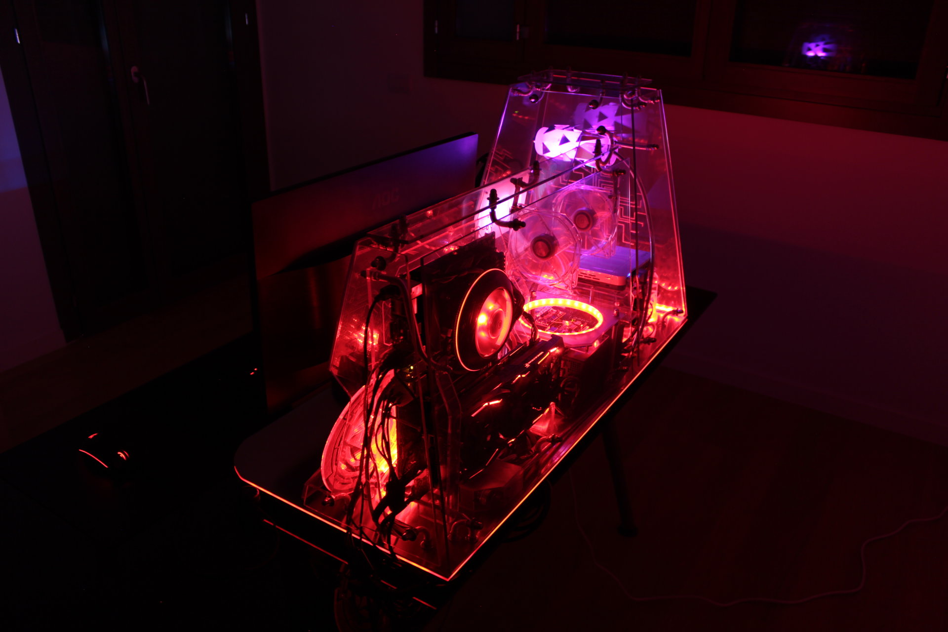
I was forgetting the fans! Here they are:
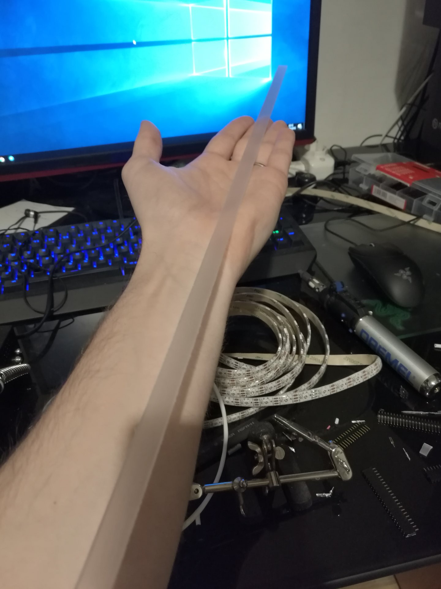
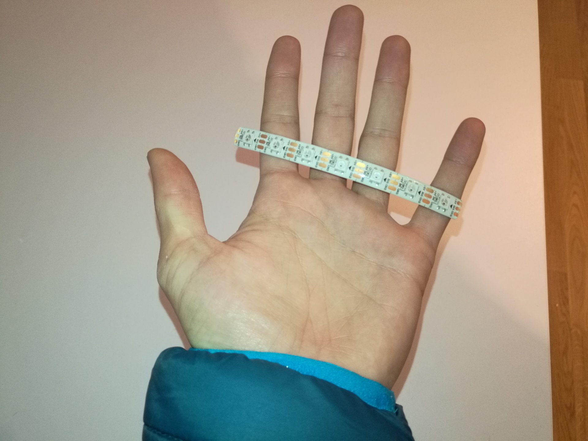
I started with 5 meters of led strip, and all I have left is this tiny piece 😀 , the rest is all in the case!
Meanwhile, in the software side, I have programmed 3 feedback effects for the proximity sensor (one for each primary color).
This effect gives to the user the feeling that the panel is “being charged” by the user’s hand! 😀
When the user bring his hand close to the sensor, the lighted panel gradually changes color (to a “more charged color”), and when the user takes back the hand, the panel returns slowly to the original color (“discharging”).
The 3 effect are:
– one starting from blue: from blue it goes gradually to green, yellow and finally red (it is the one visible in this video below)
– one starting from red, that mimics the incandescent metal: from red it goes to orange, yellow and finally white
– one starting from green, that goes to white
Then I modified the KernelController application, to automatically sync the projected animations with the lighting states:
And then I modified the effect of the “running pixel with trail”, adding more pixels at once!
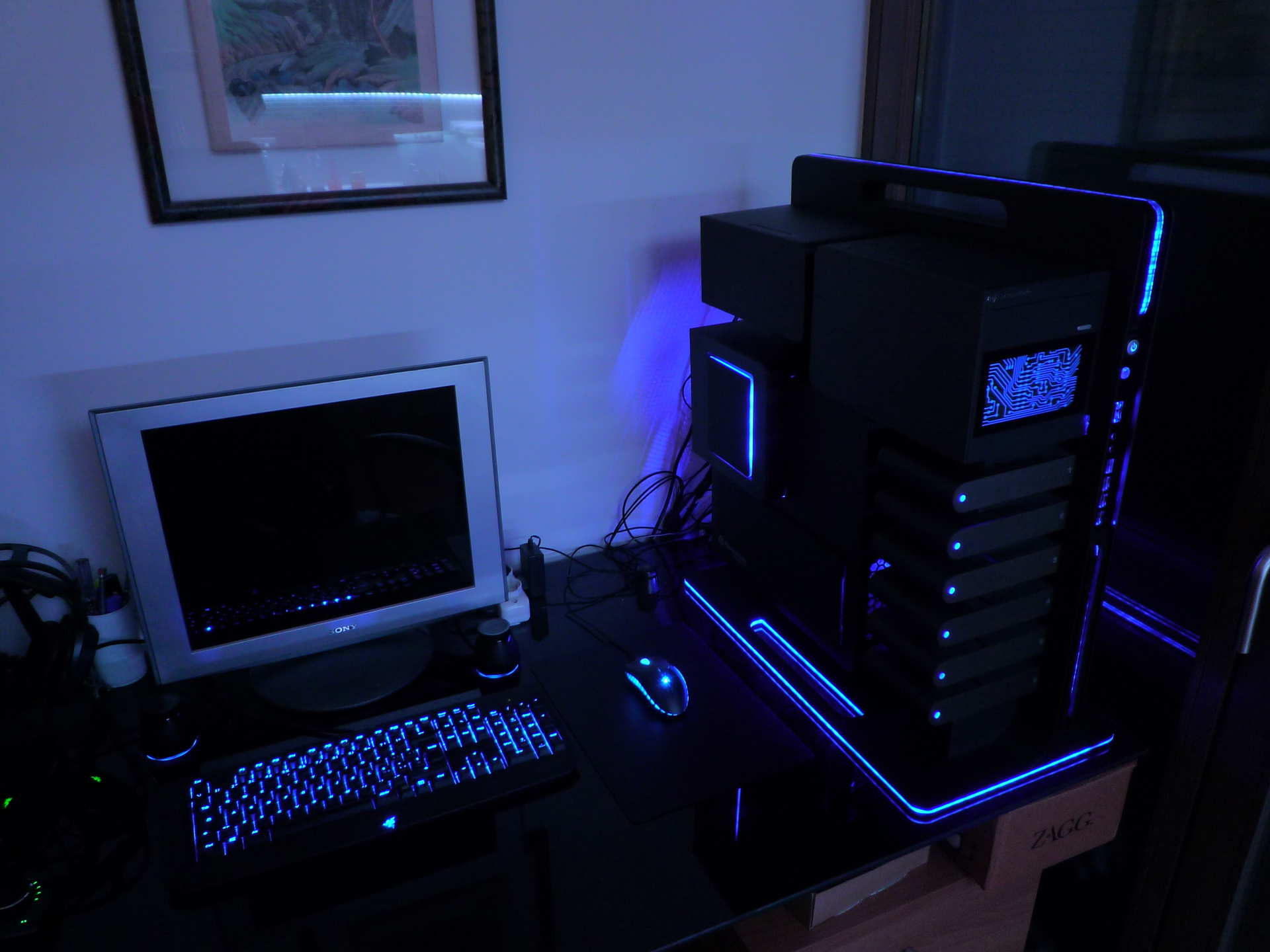
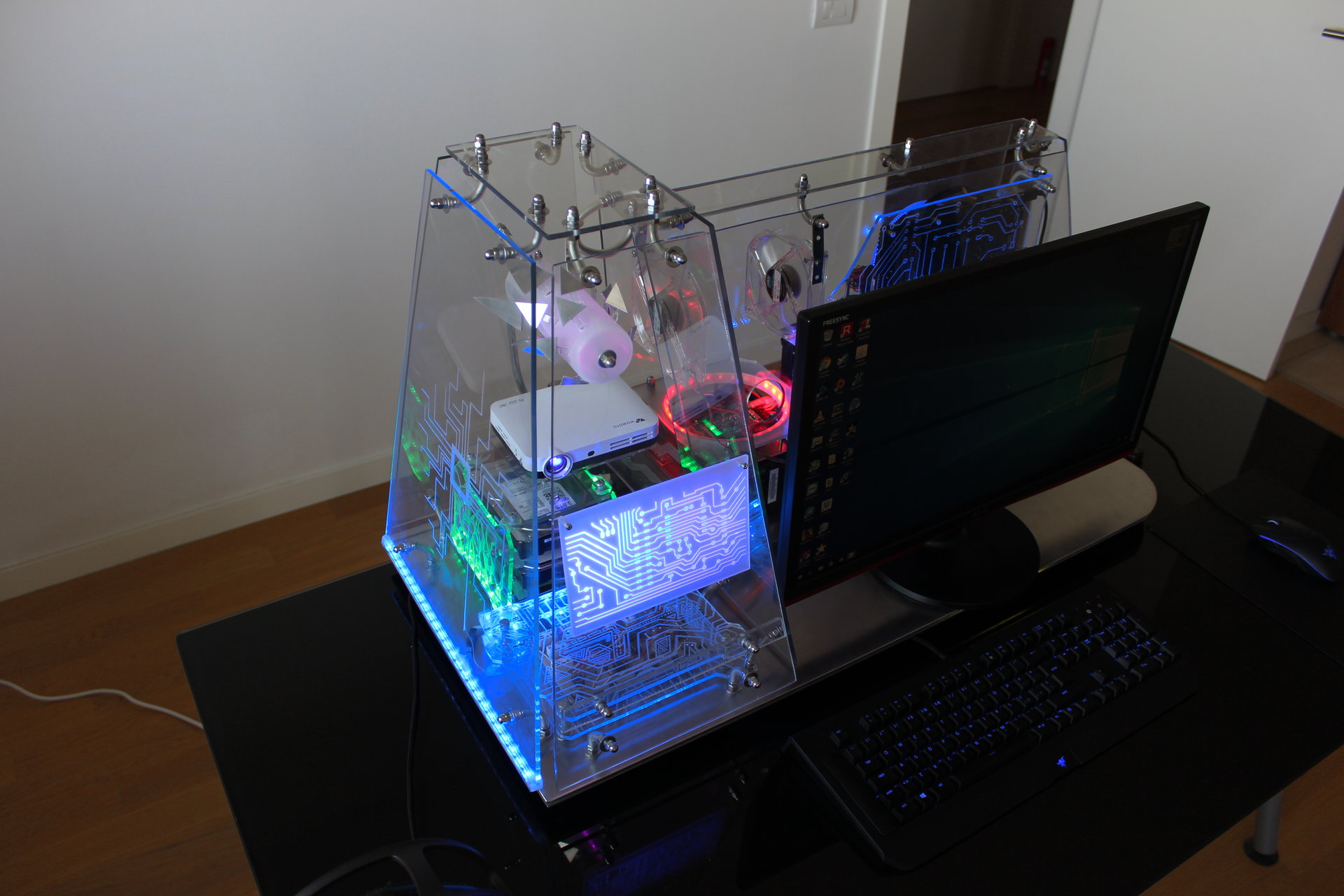
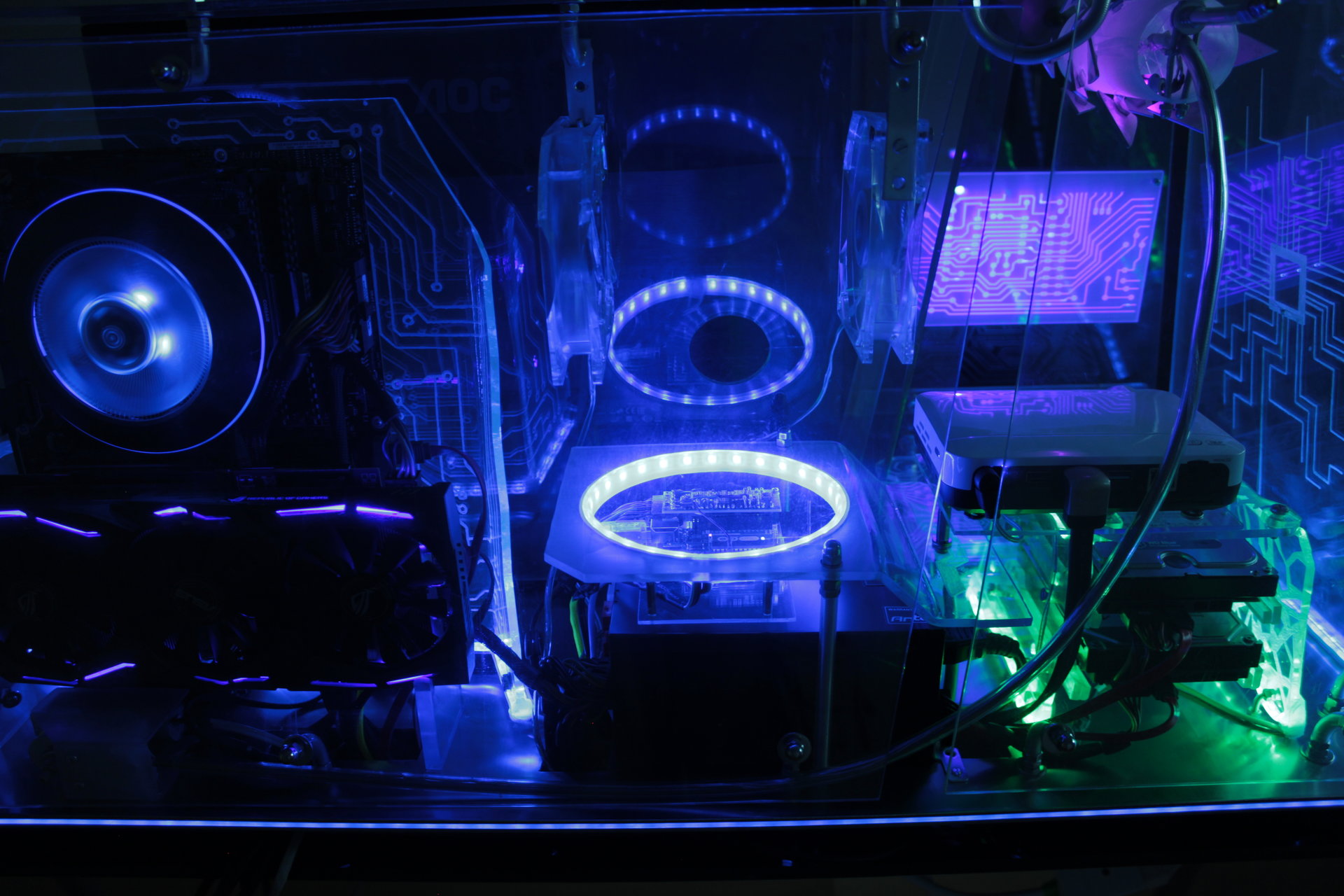
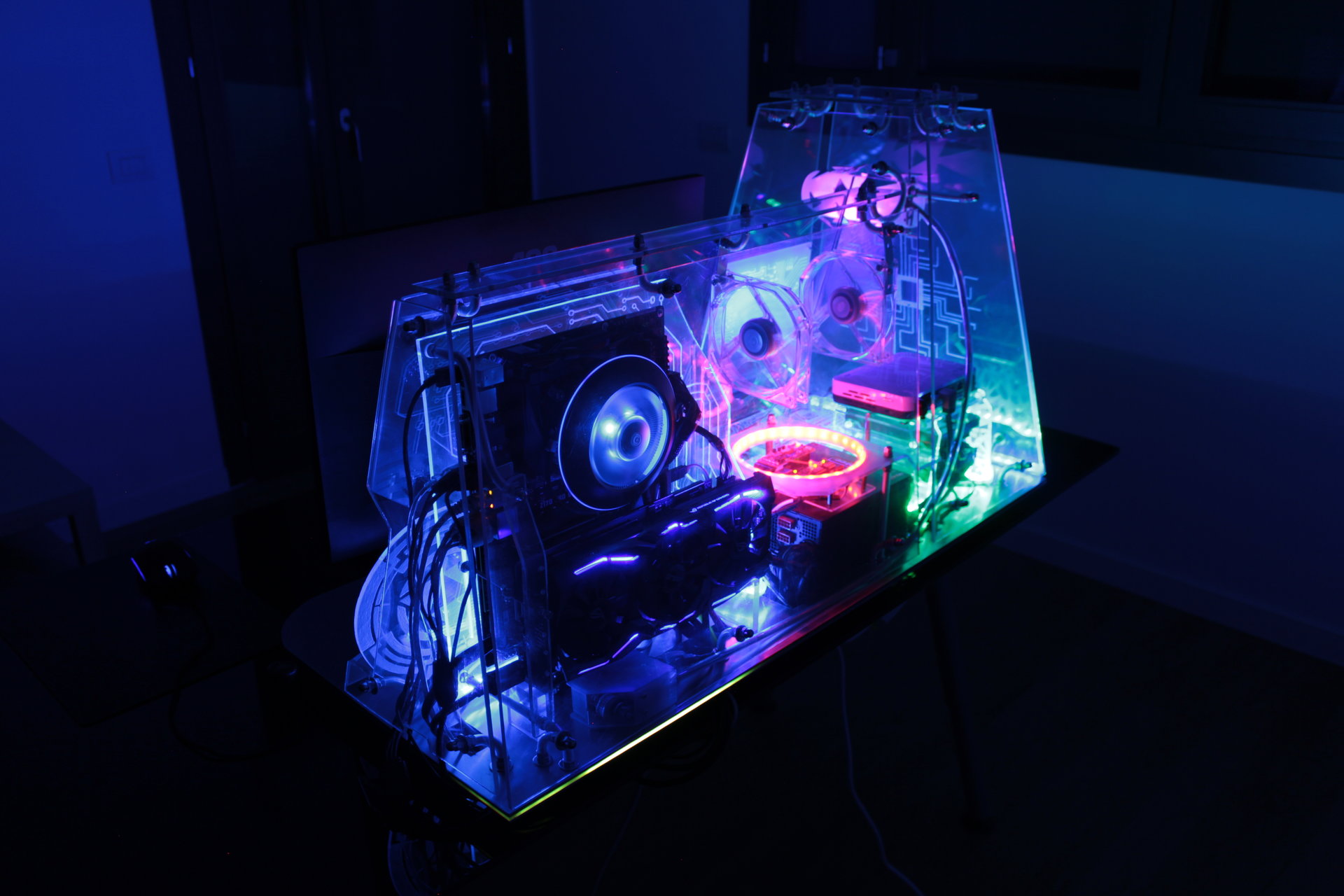
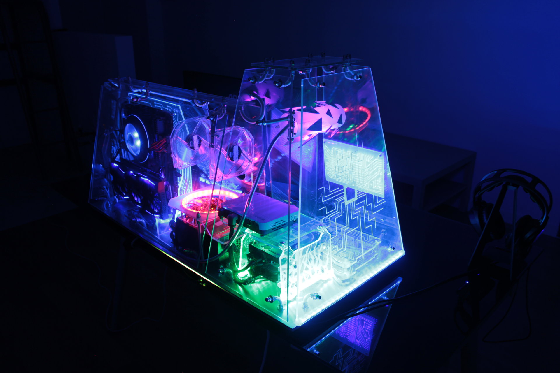
This is the result on the ring and around the base (the pixels running around the base remind me the Tron lightcycles 😀 ):
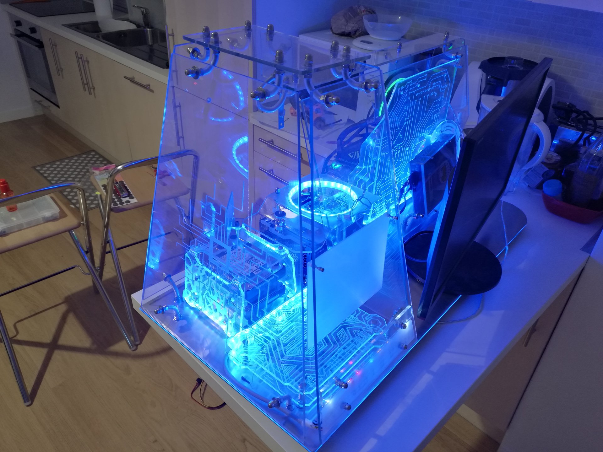
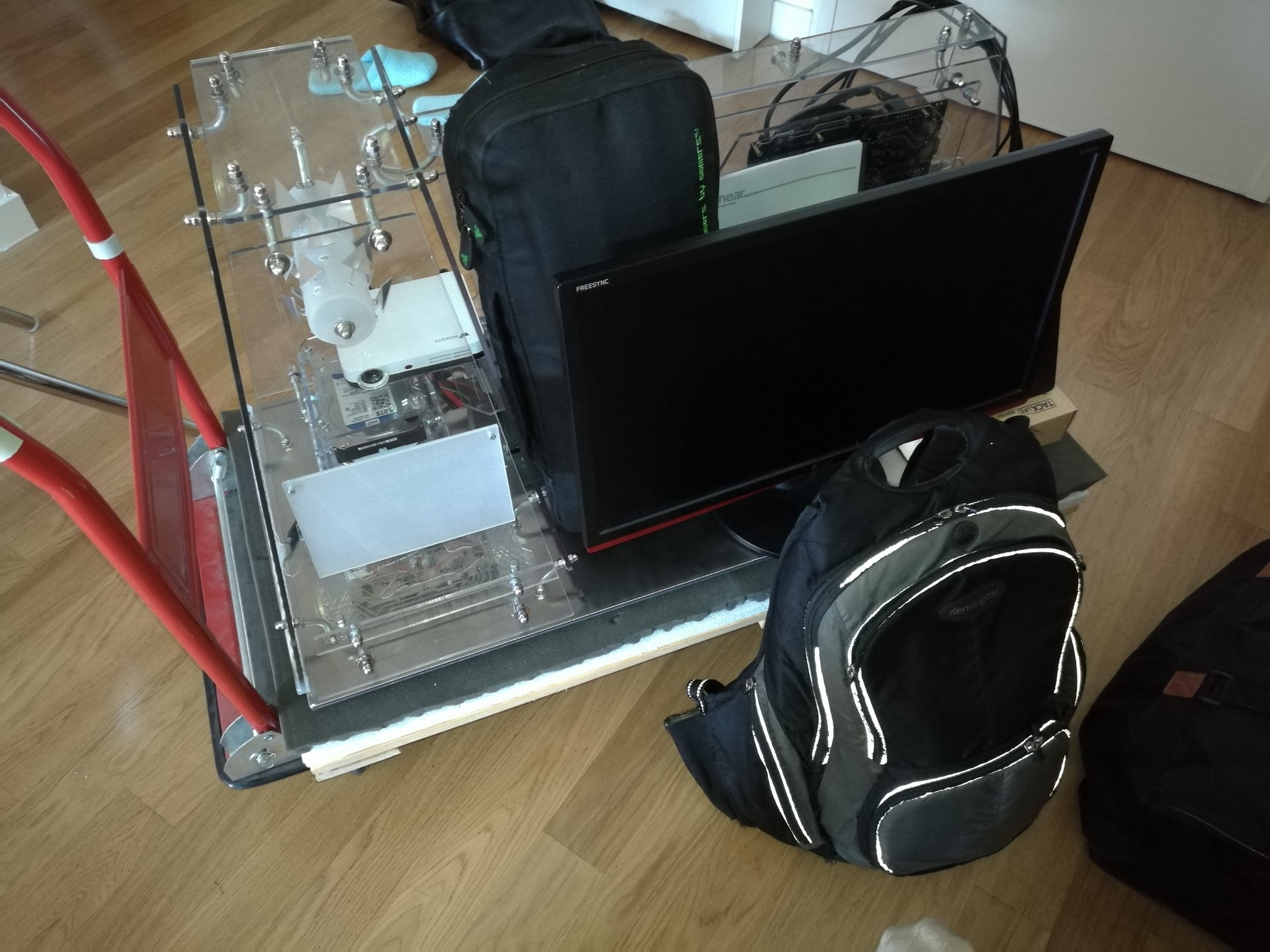
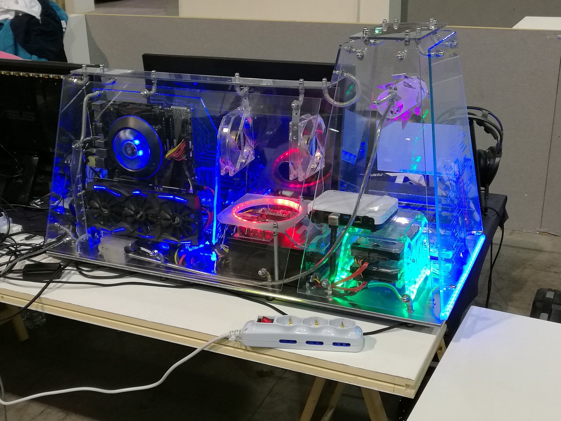
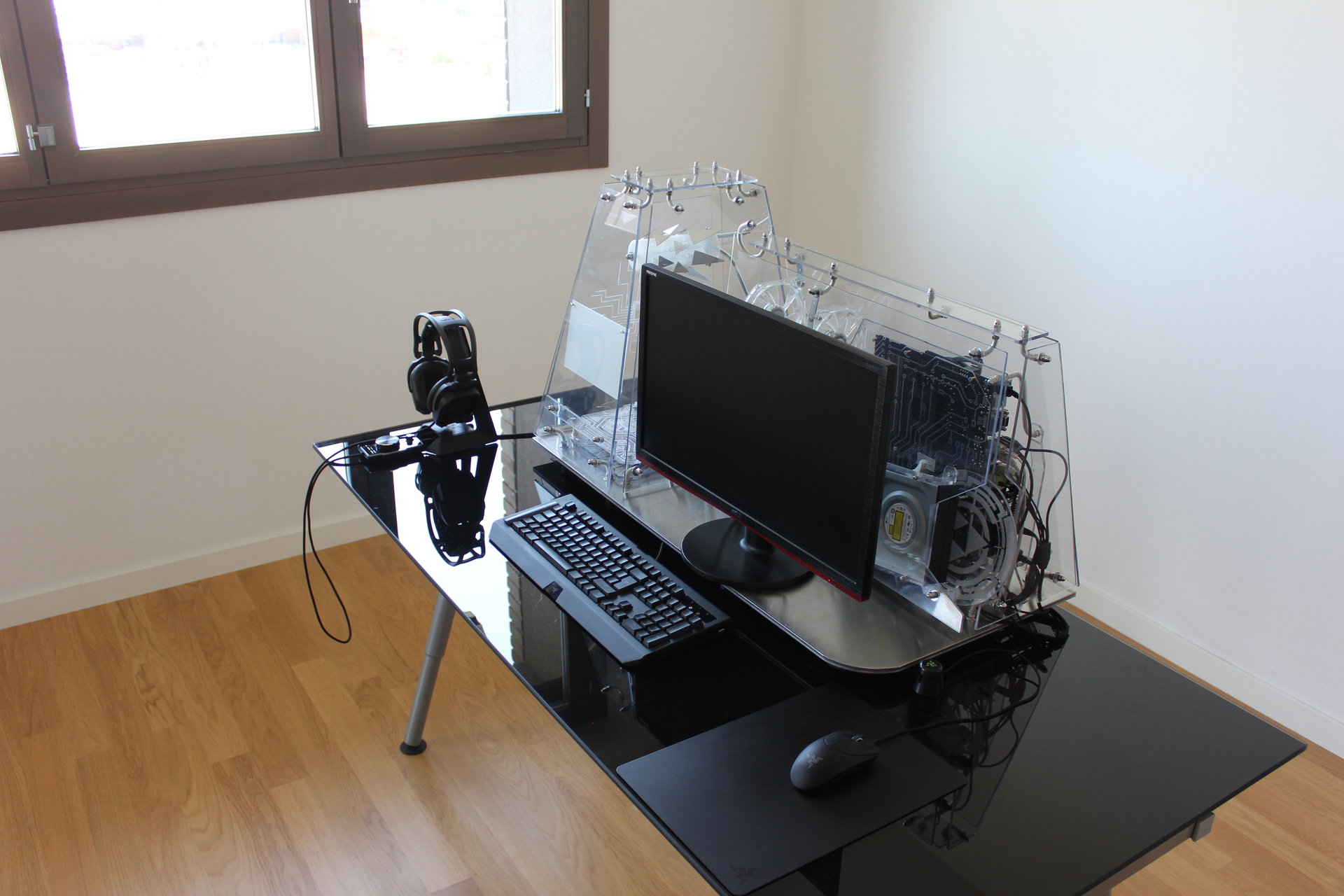
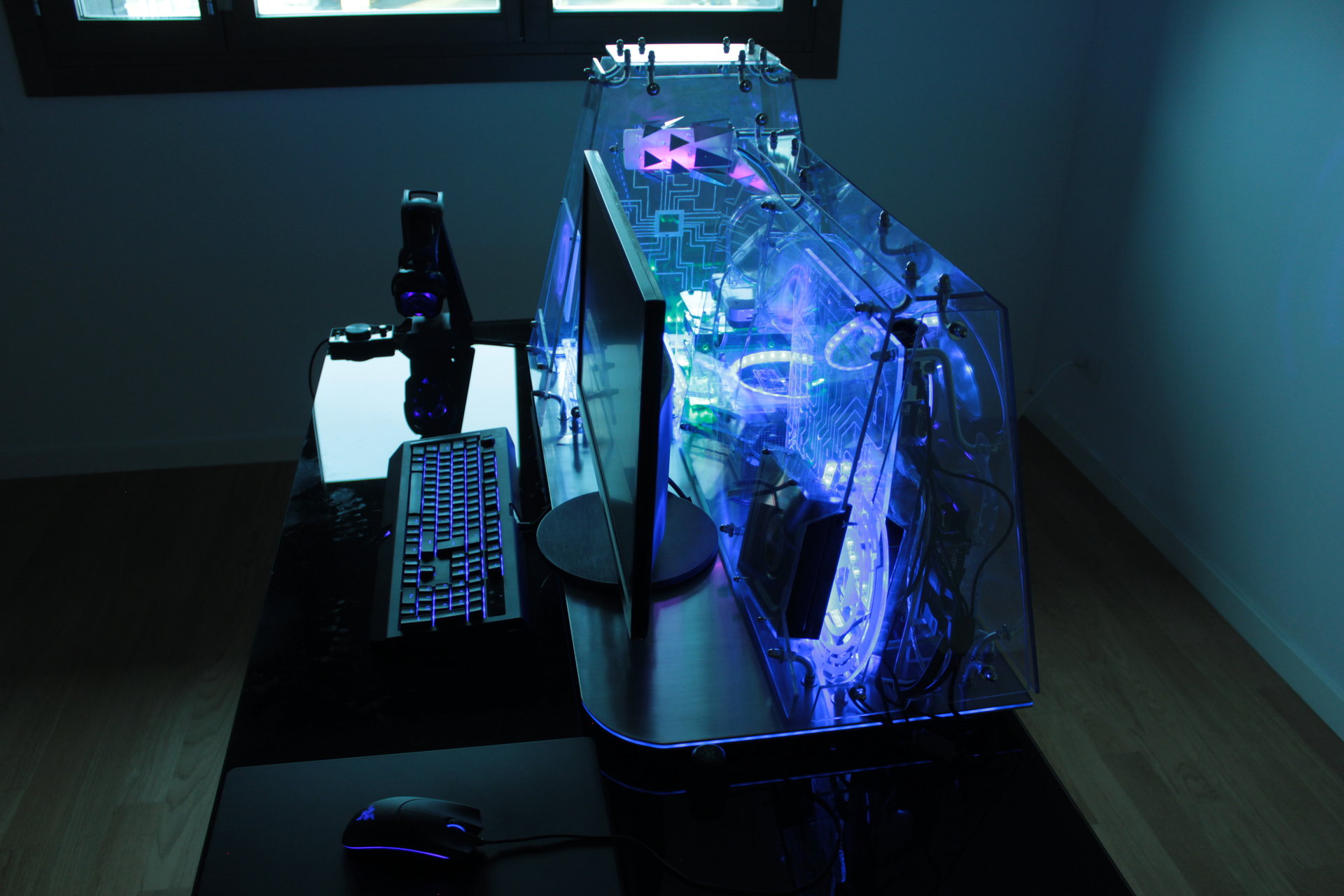
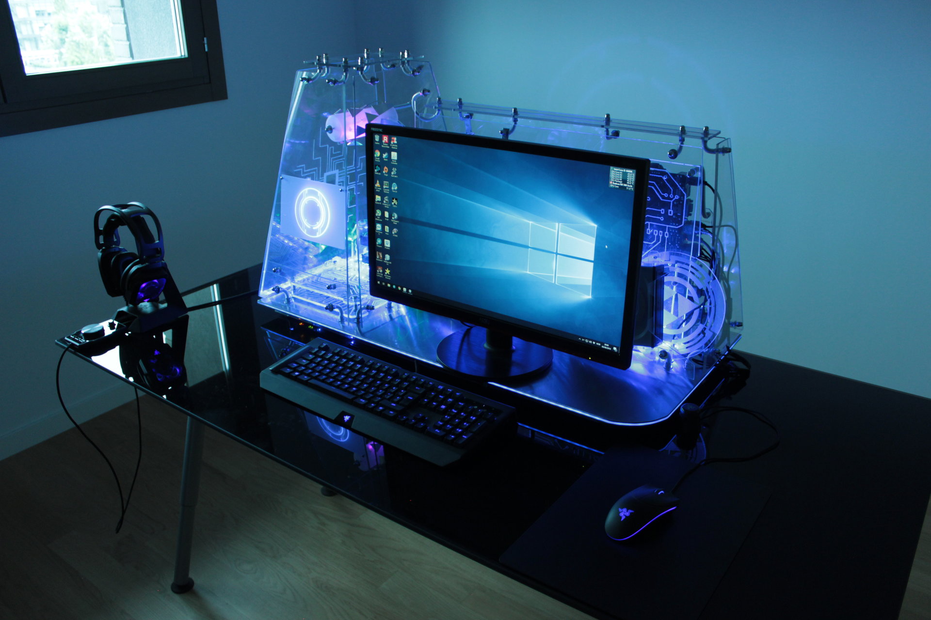
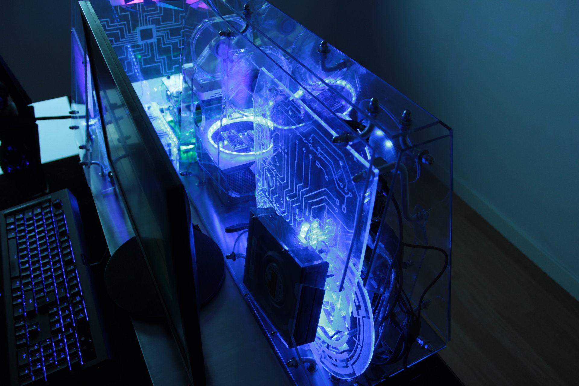
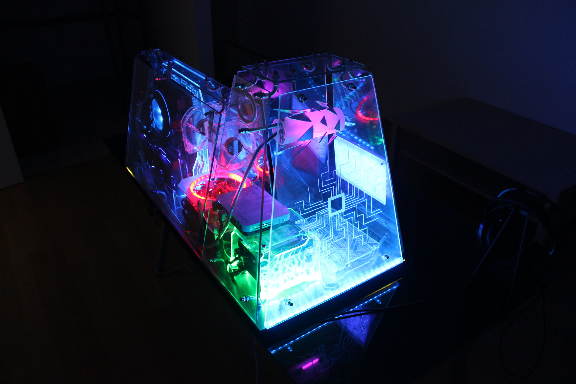
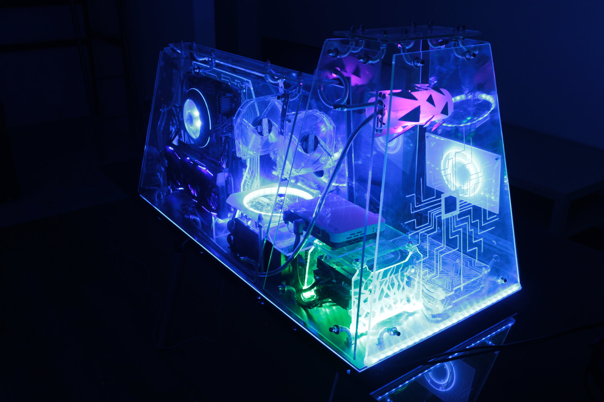
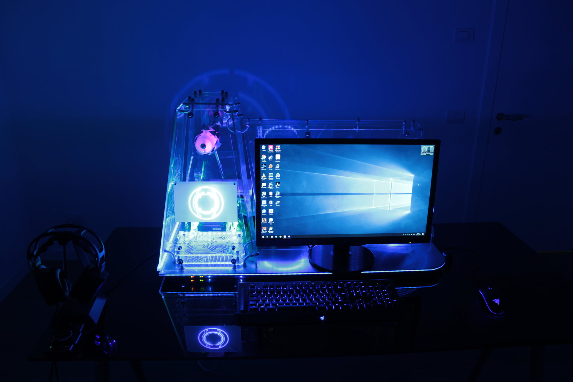
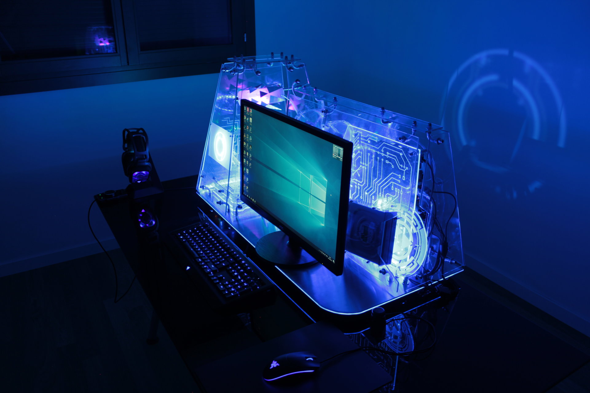
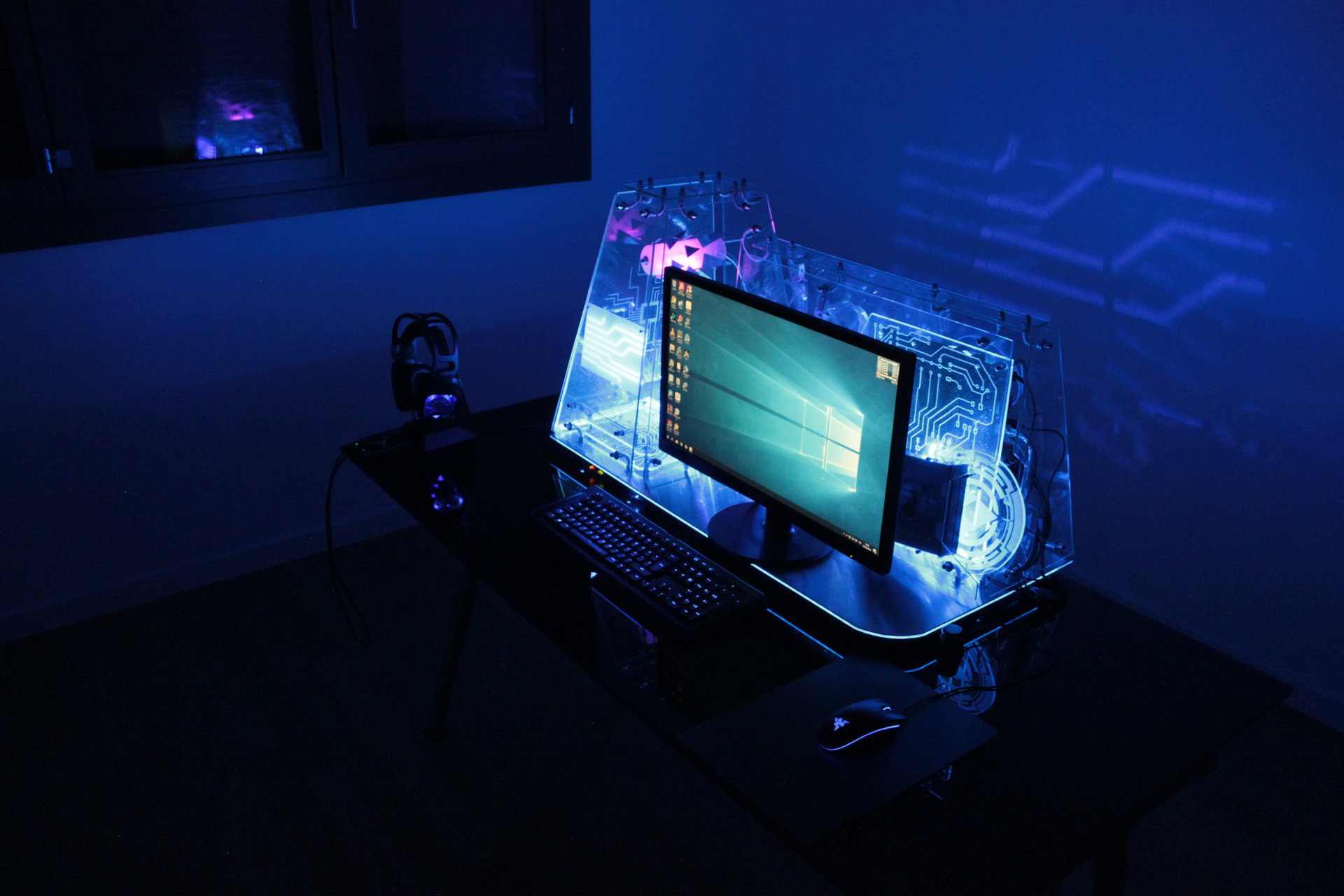
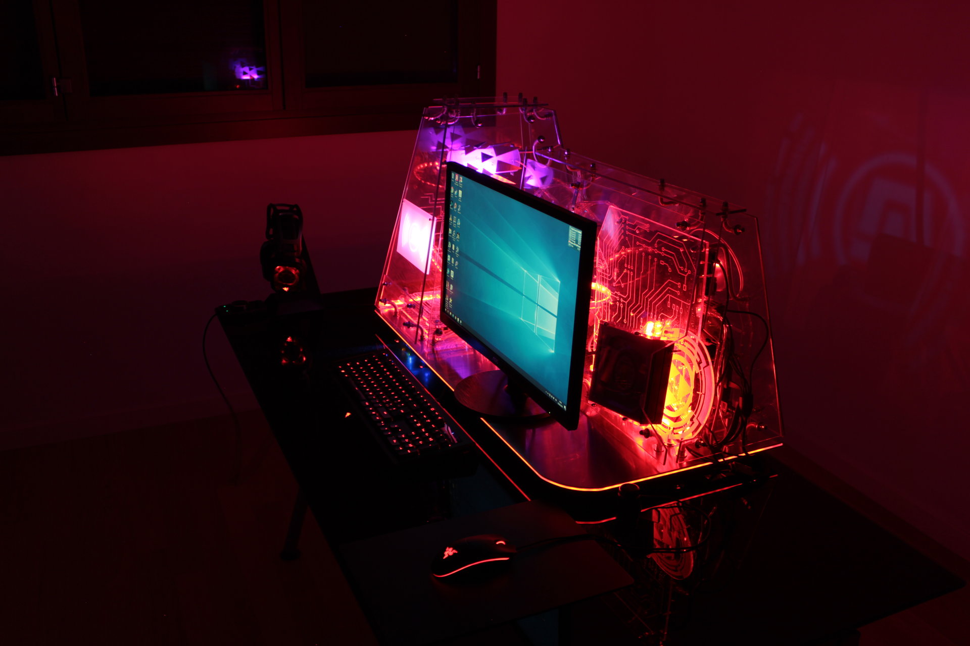
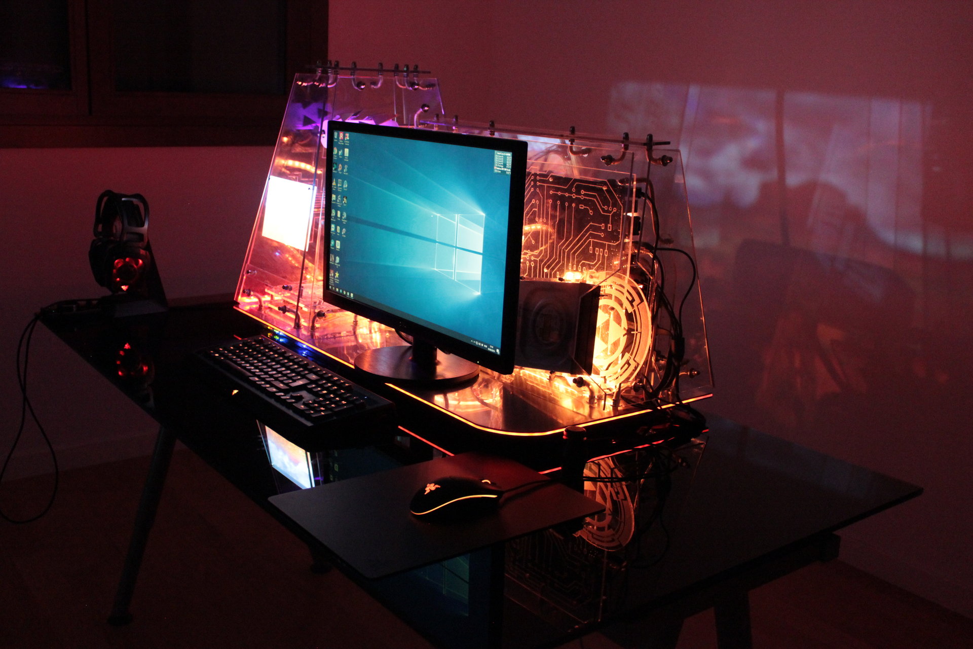
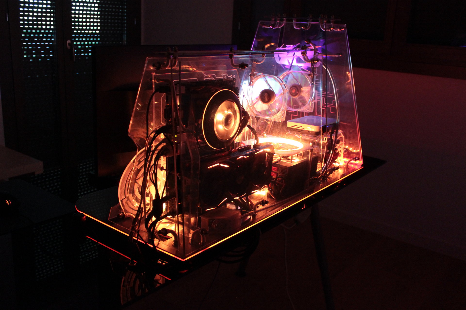
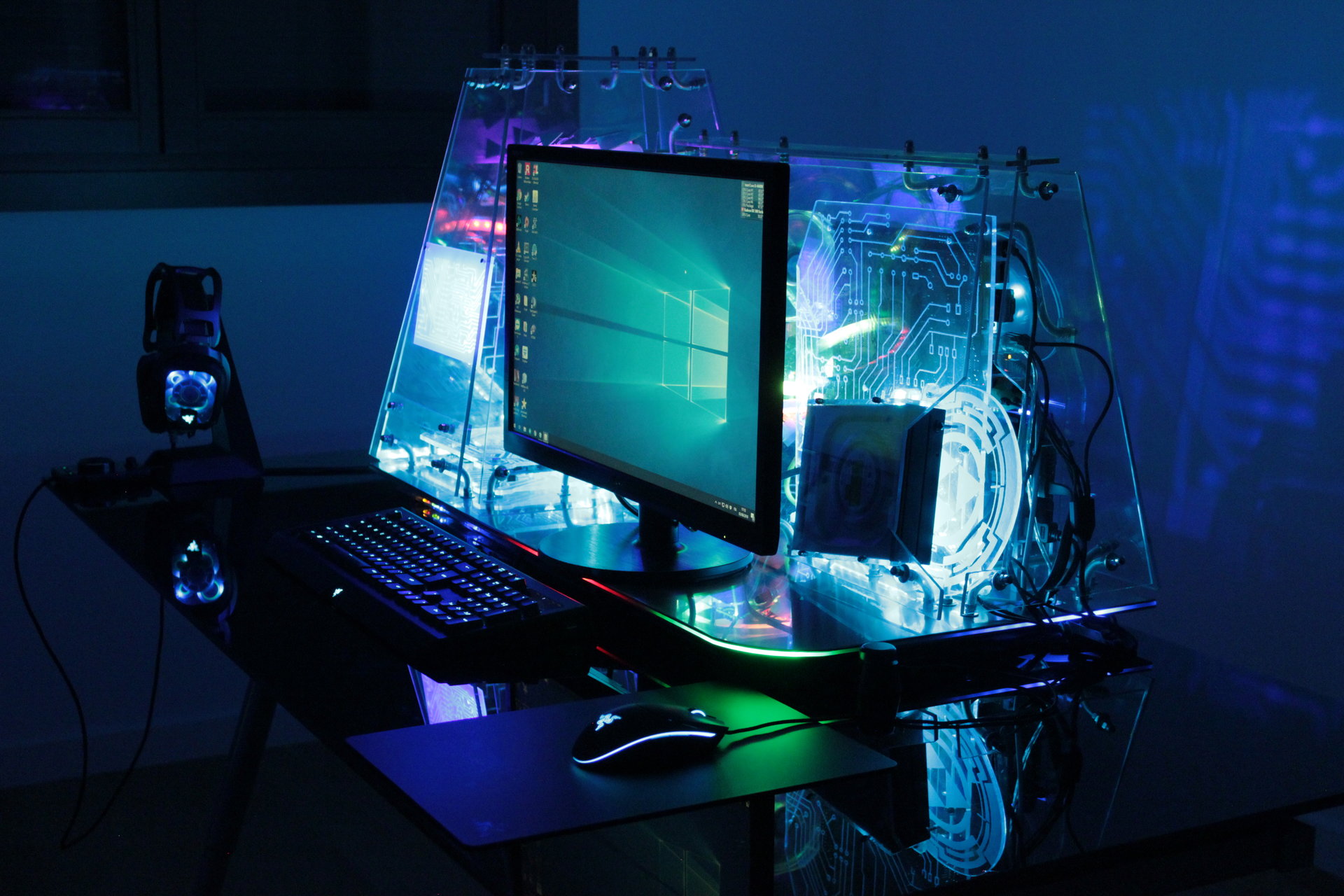
And finally this is the inauguration of the completed Kernel 2.0!!! I have taken it to a lan party! 😀
These are two short videos taken at the lan party:
This is the video of all the features of the mod (in particular all the animations and the moving parts)!
NOTE: the video has english subtitles, that can be activated from the youtube interface
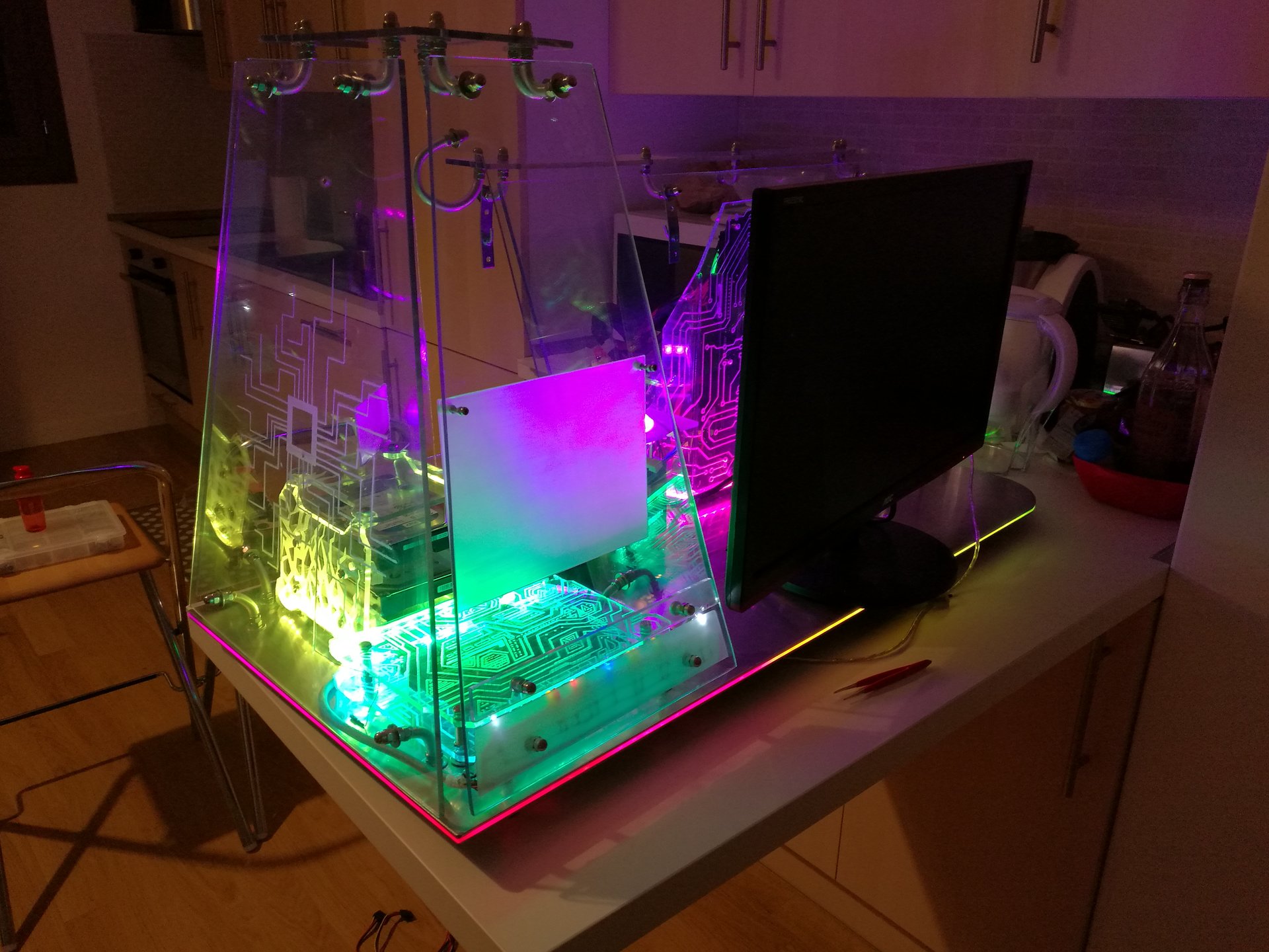
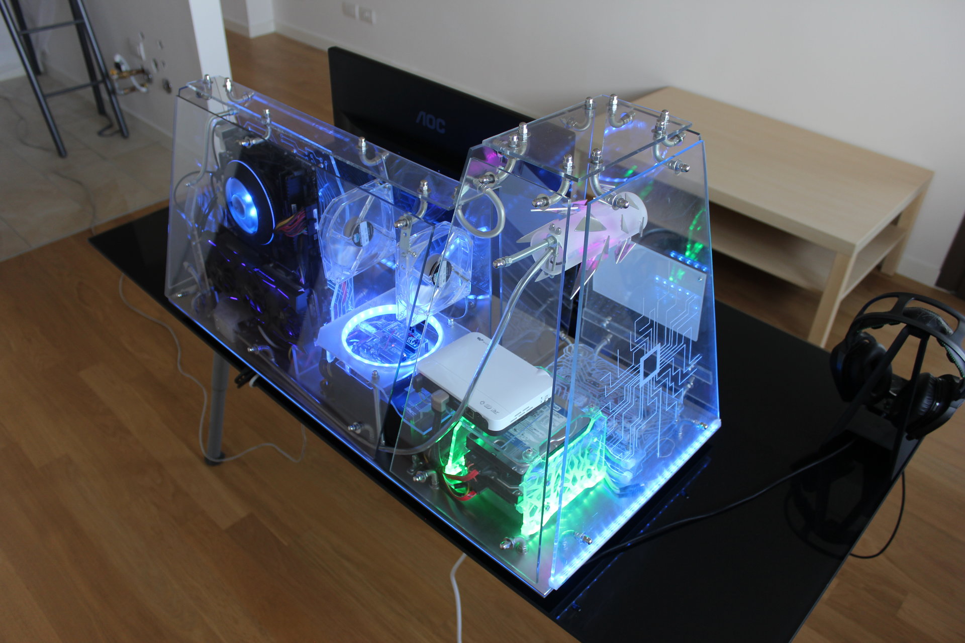
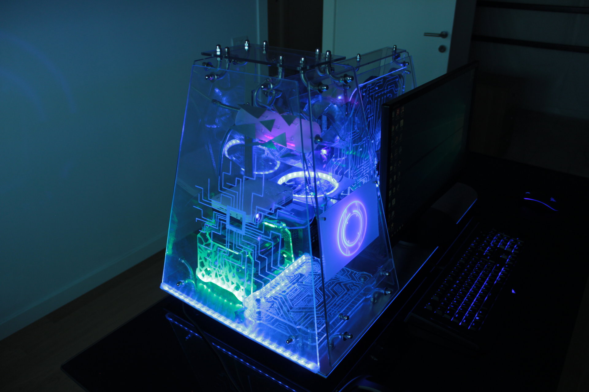
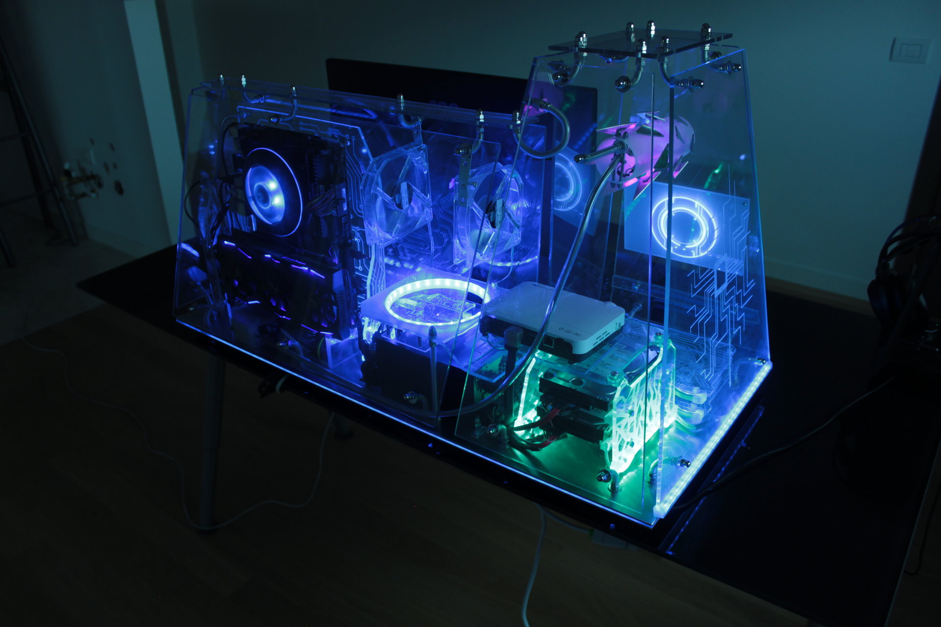
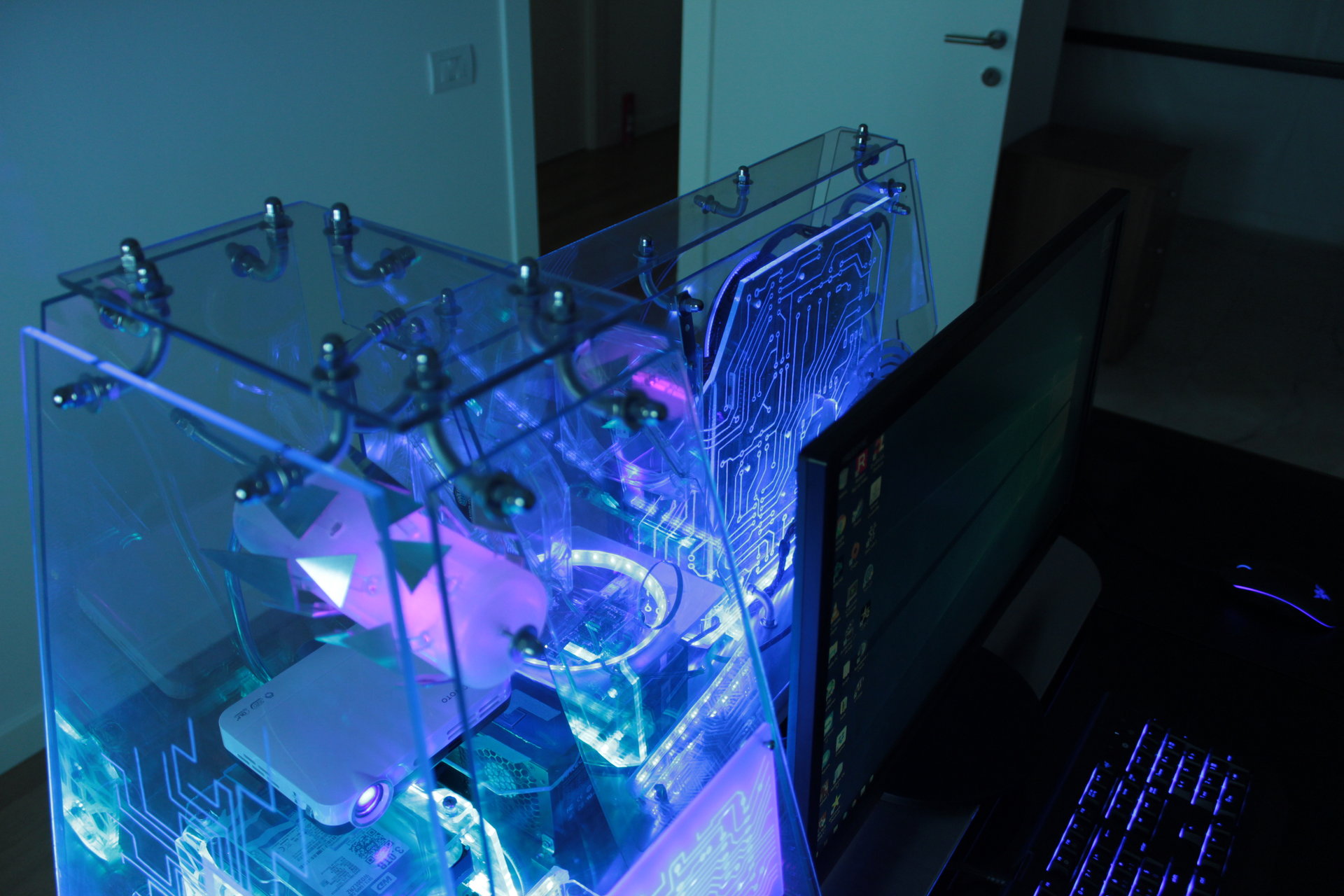
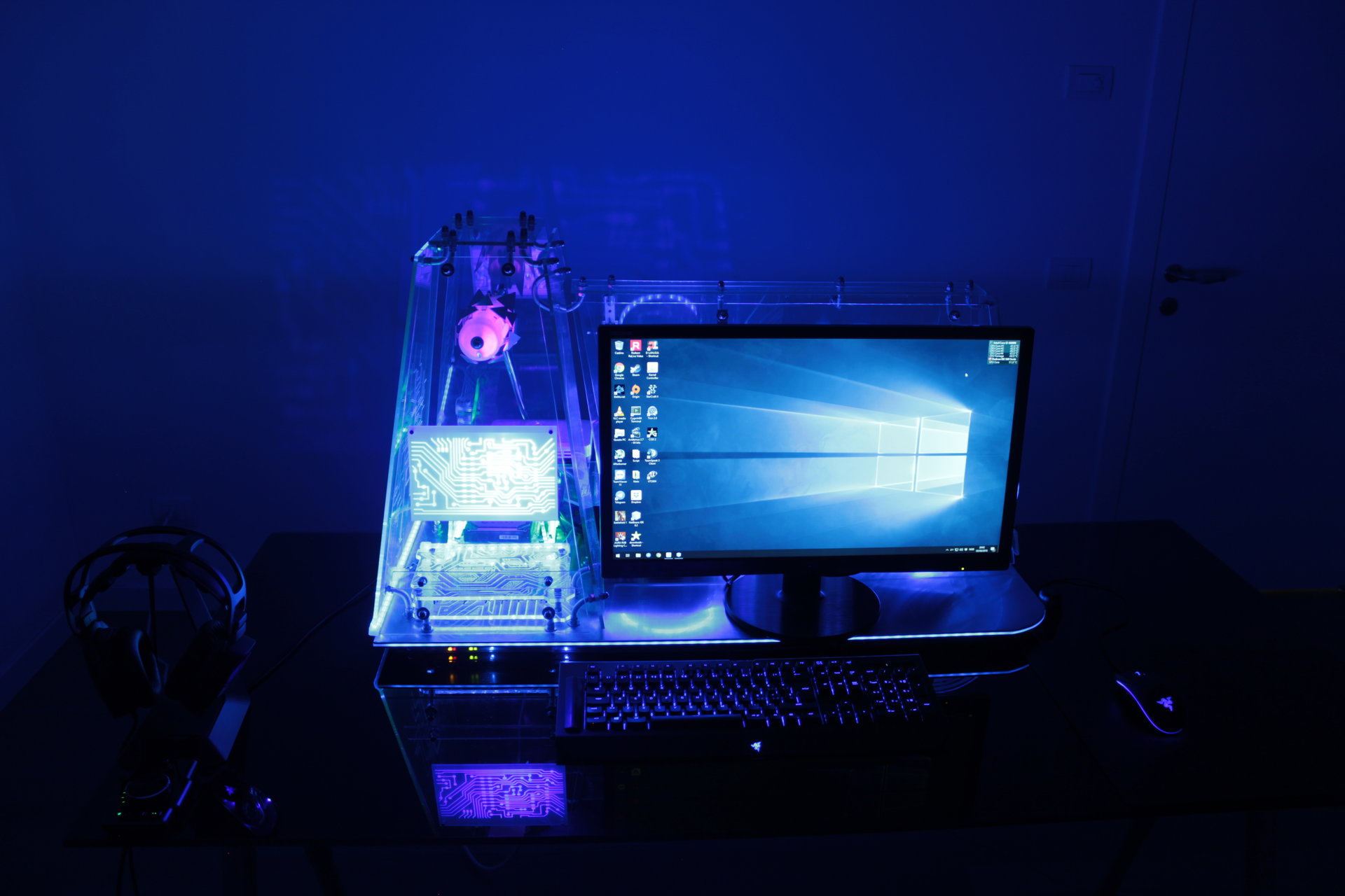
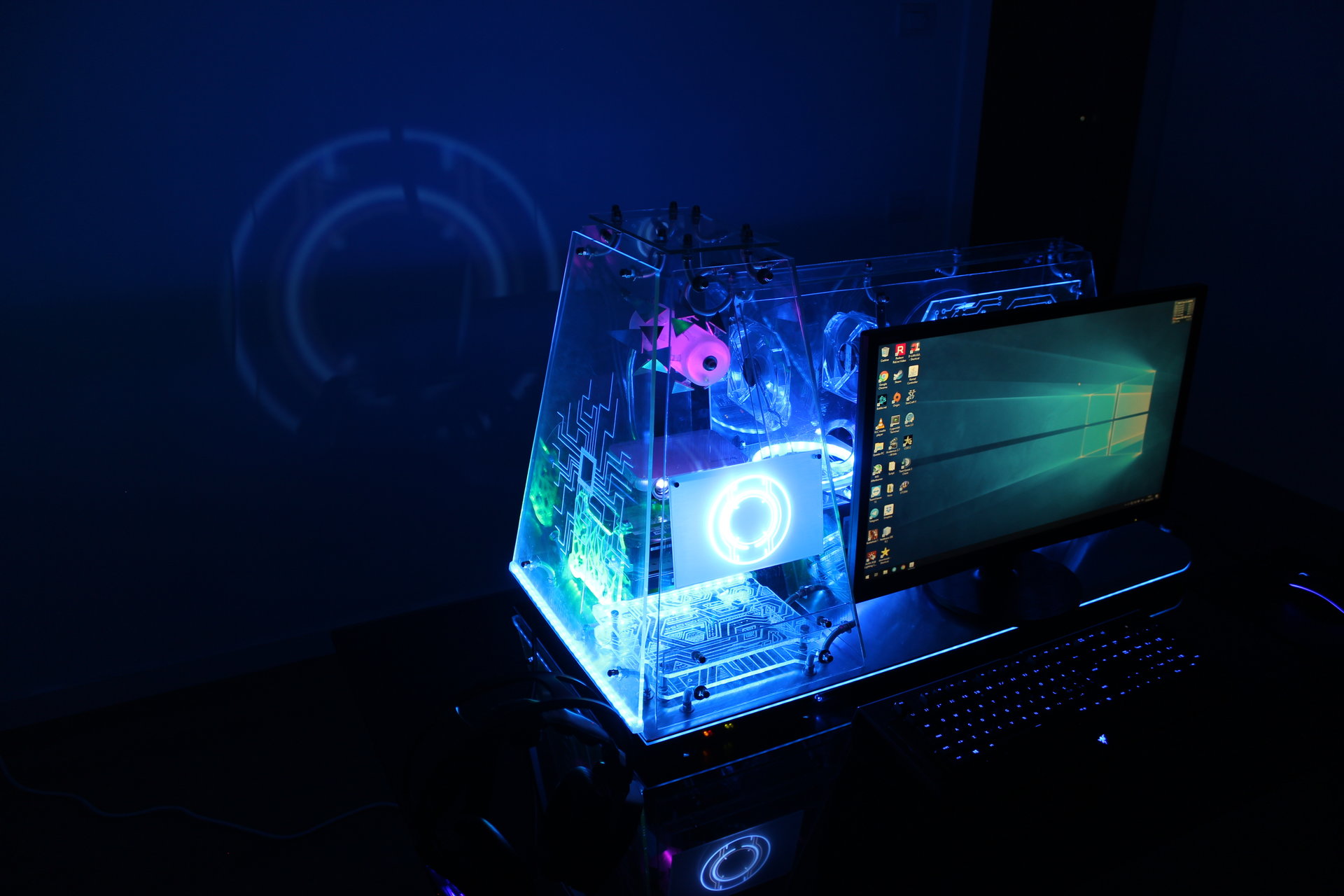
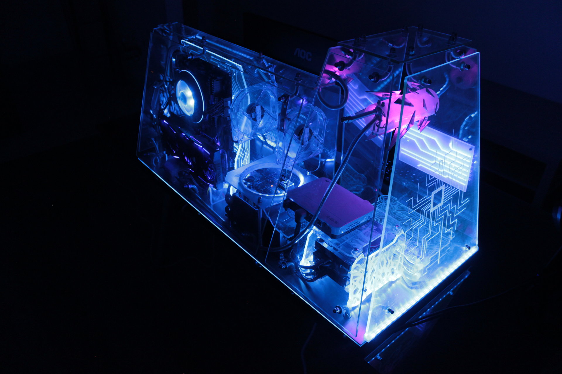
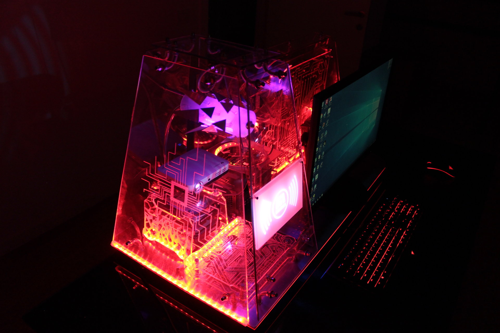
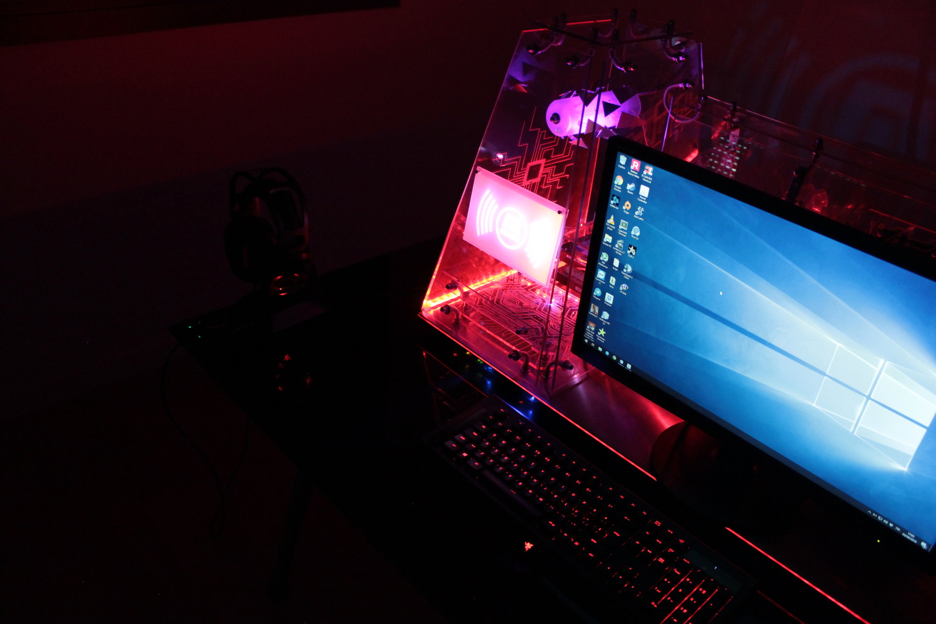
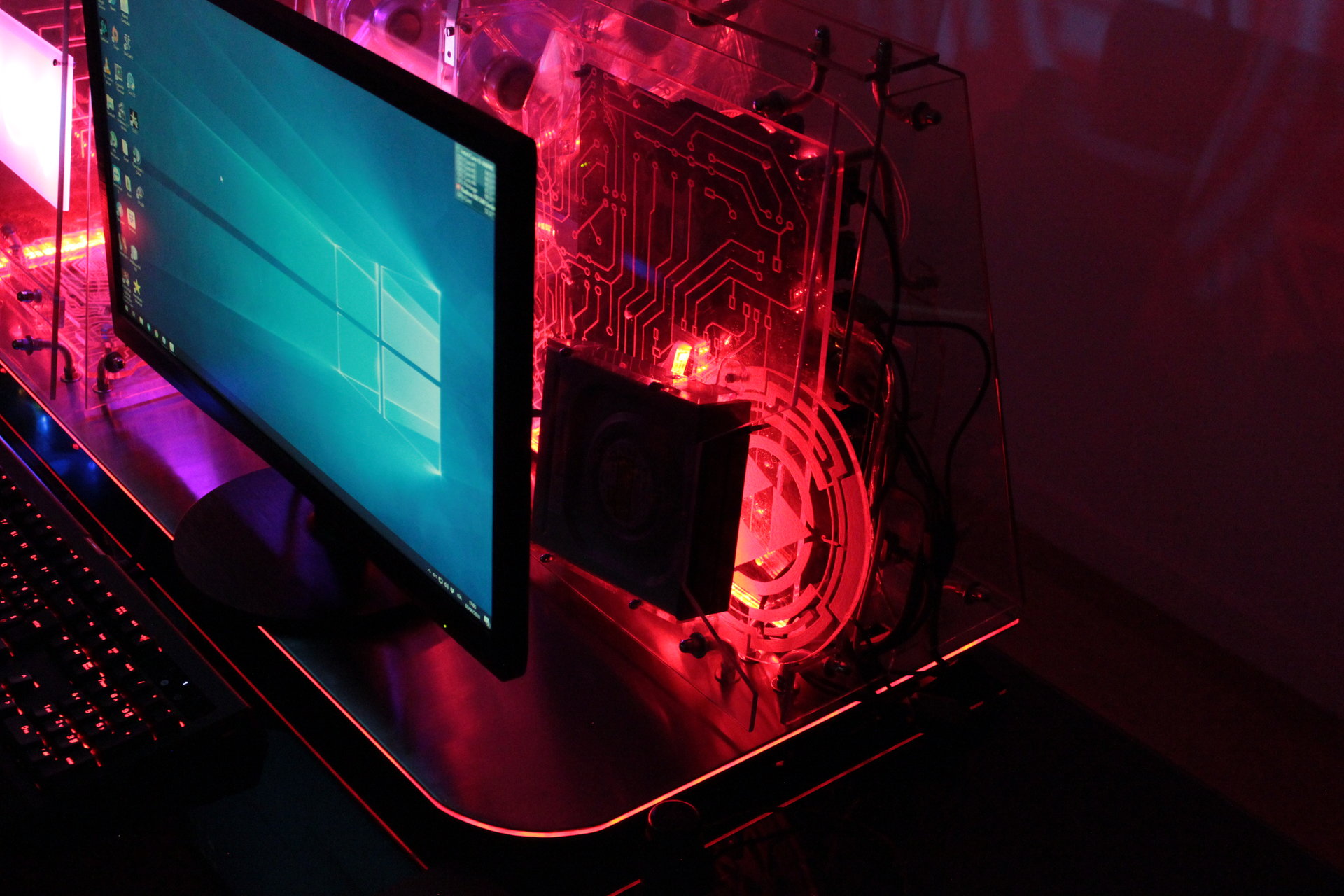
And these are all the pics, divided by lighting state:
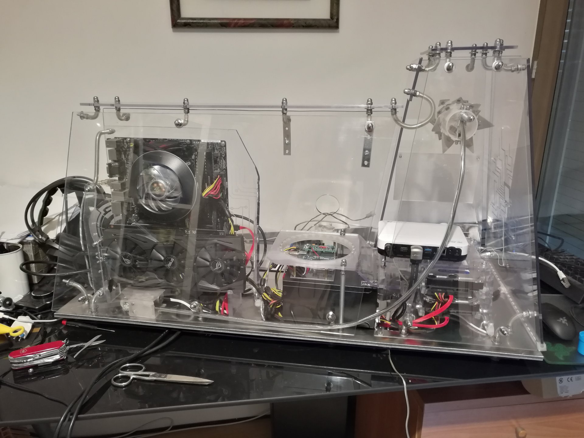
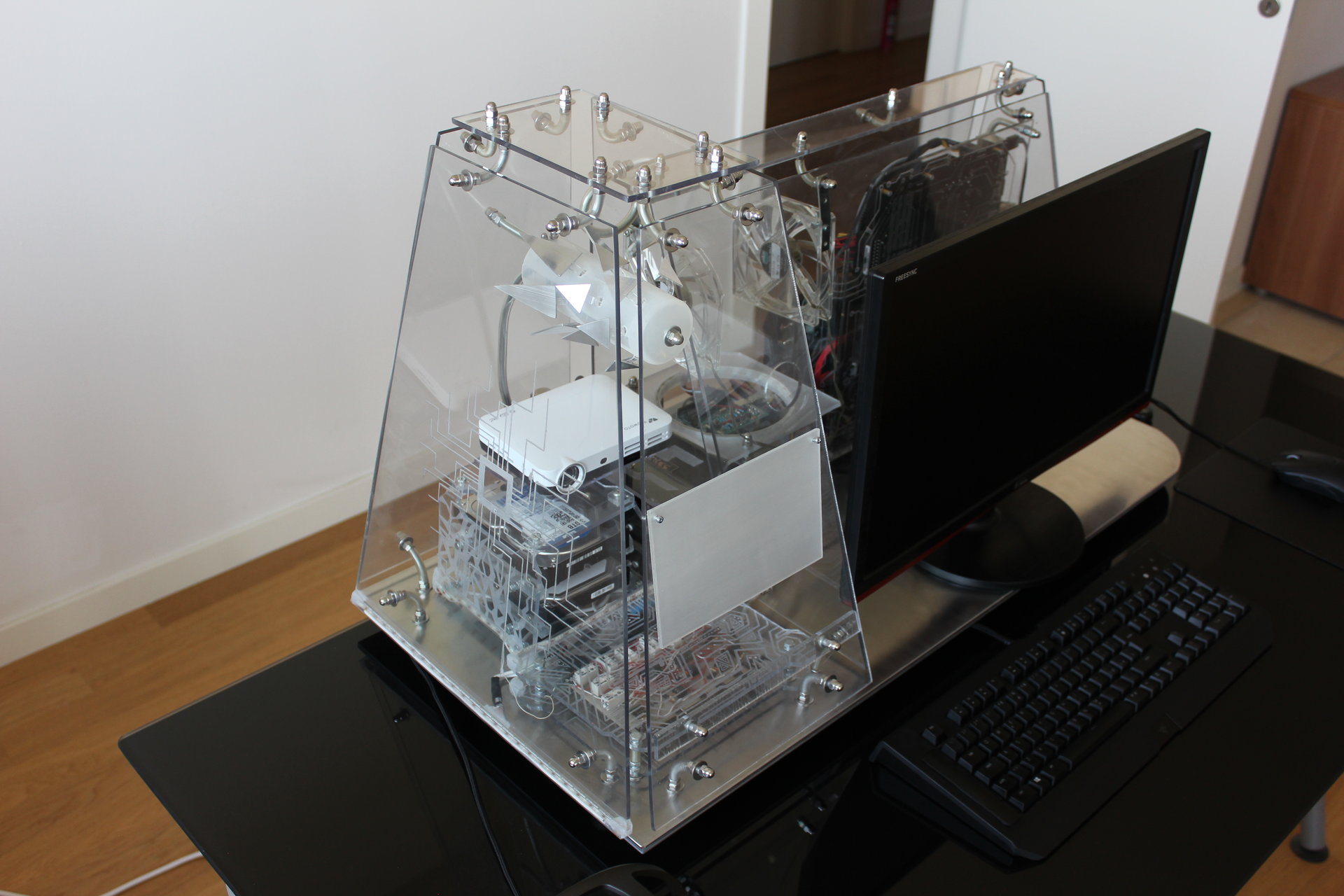
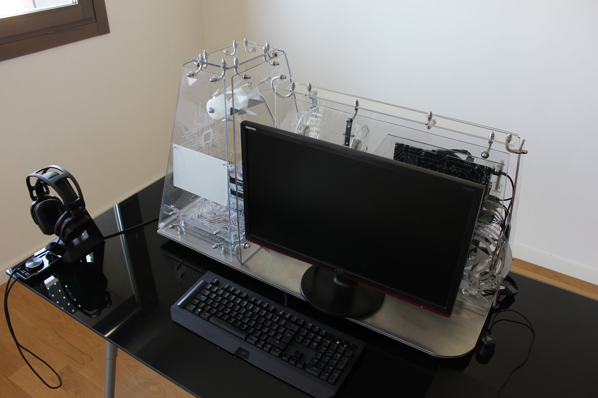
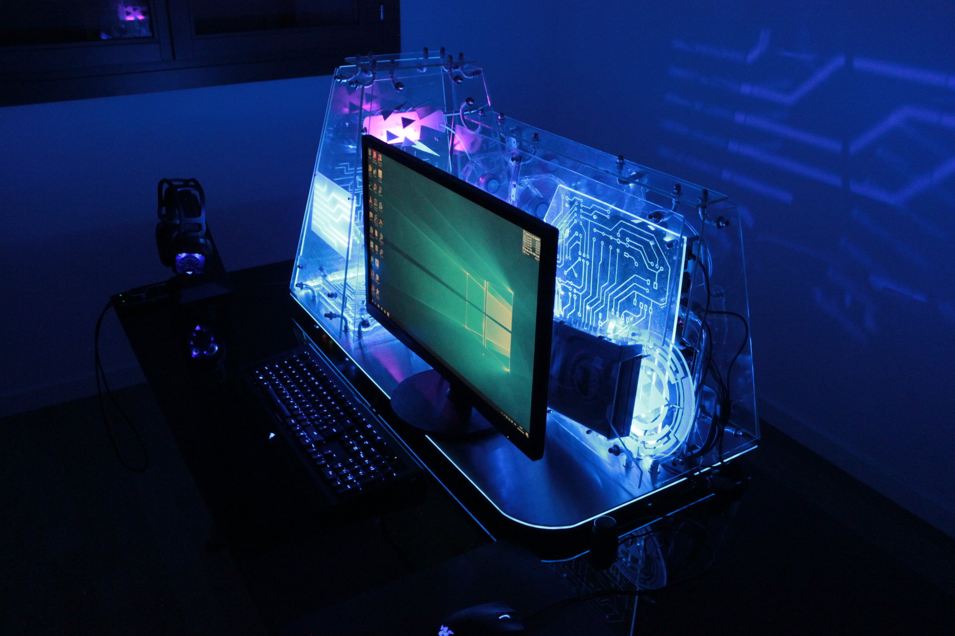
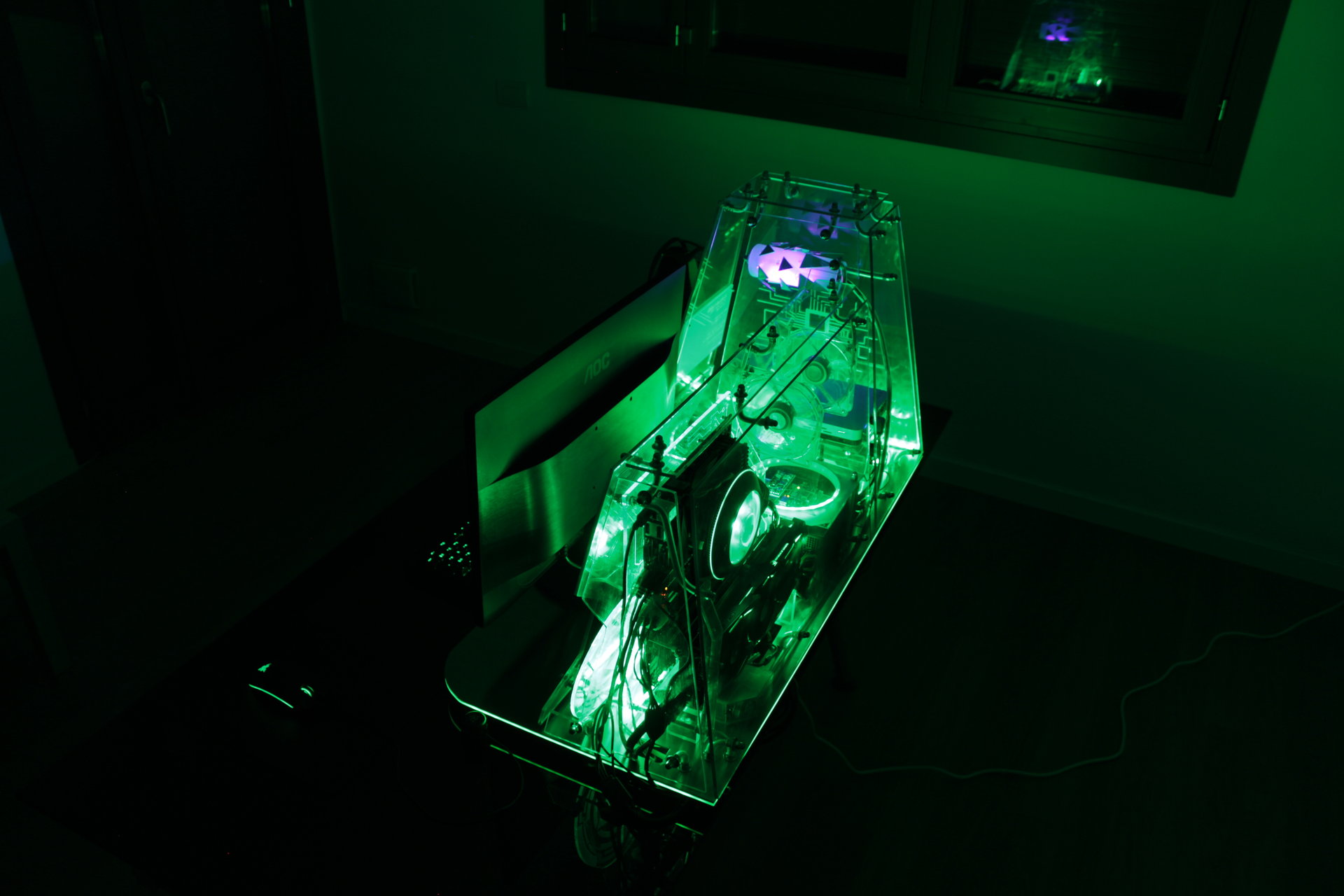
The powered off PC:
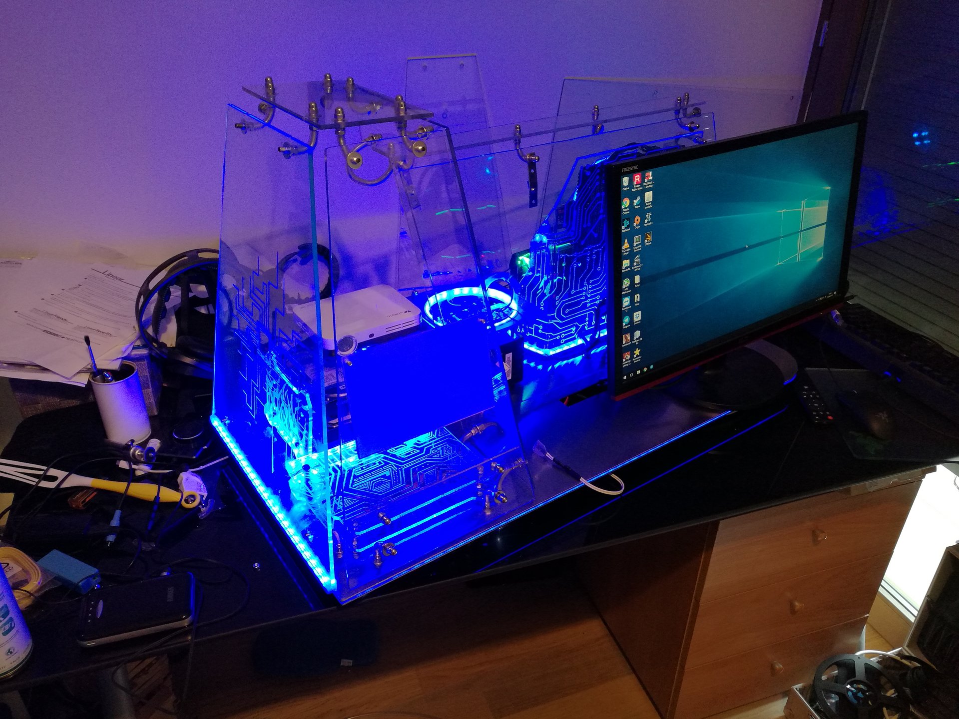
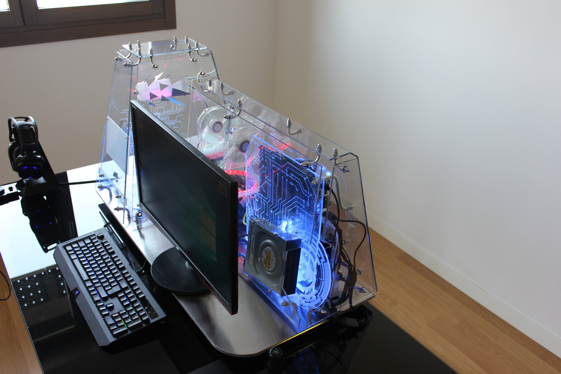
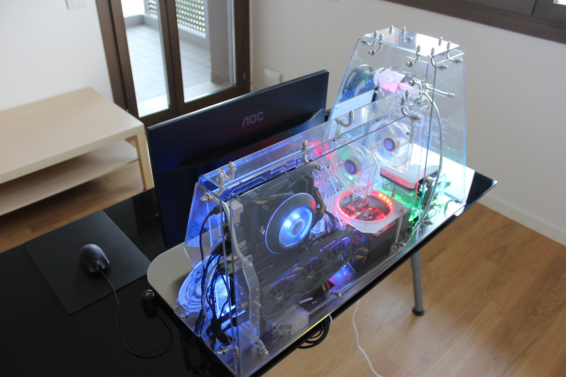
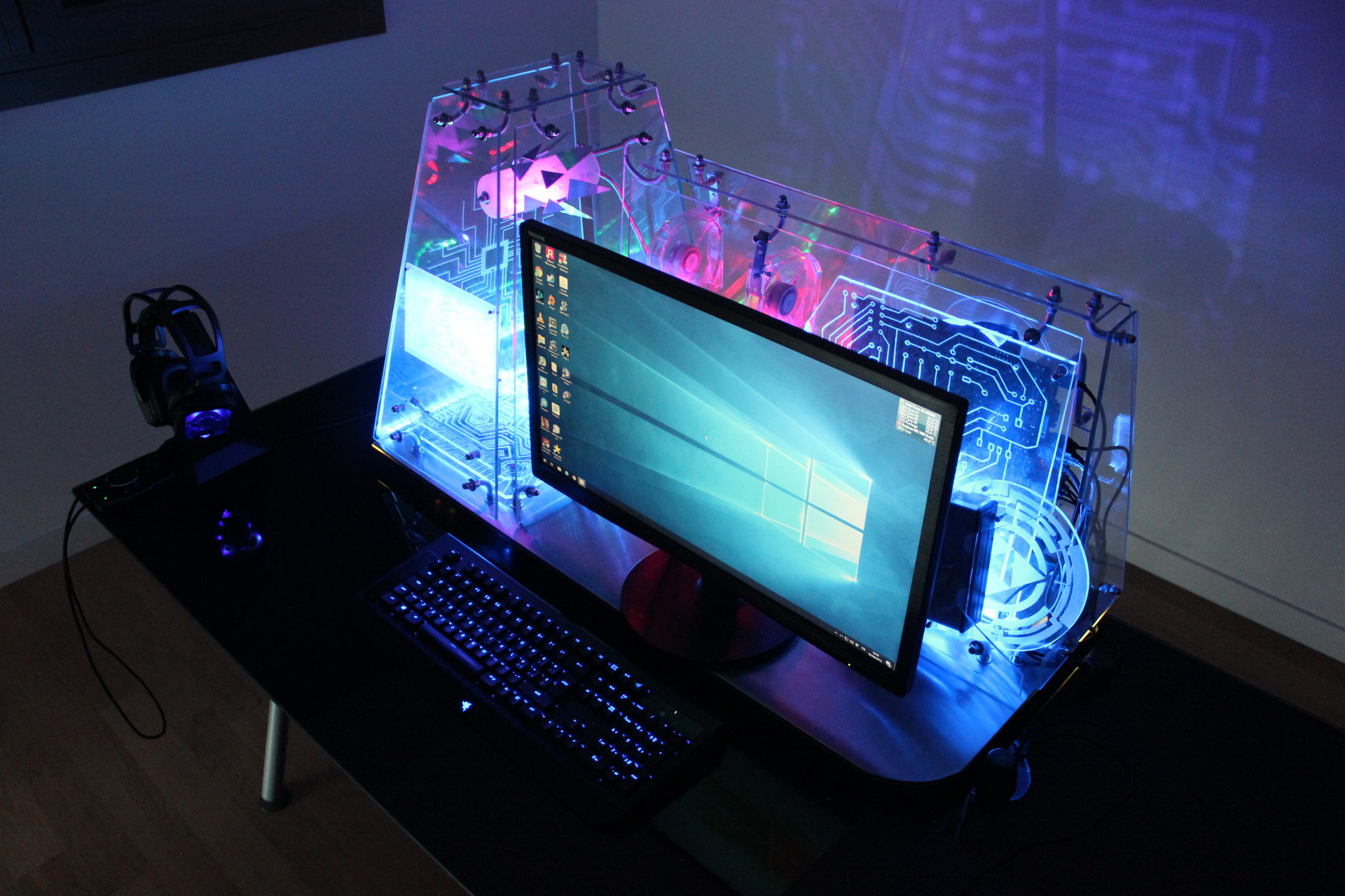
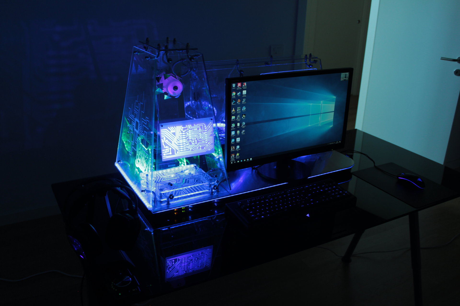
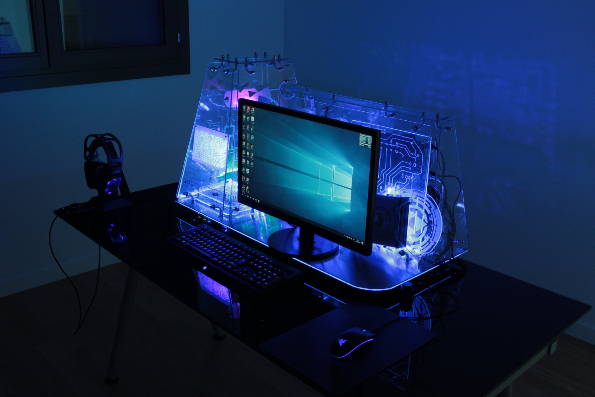
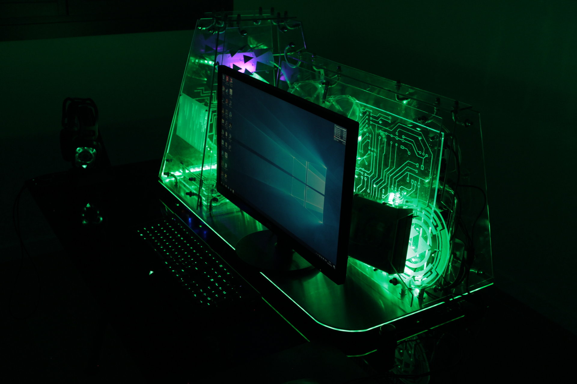
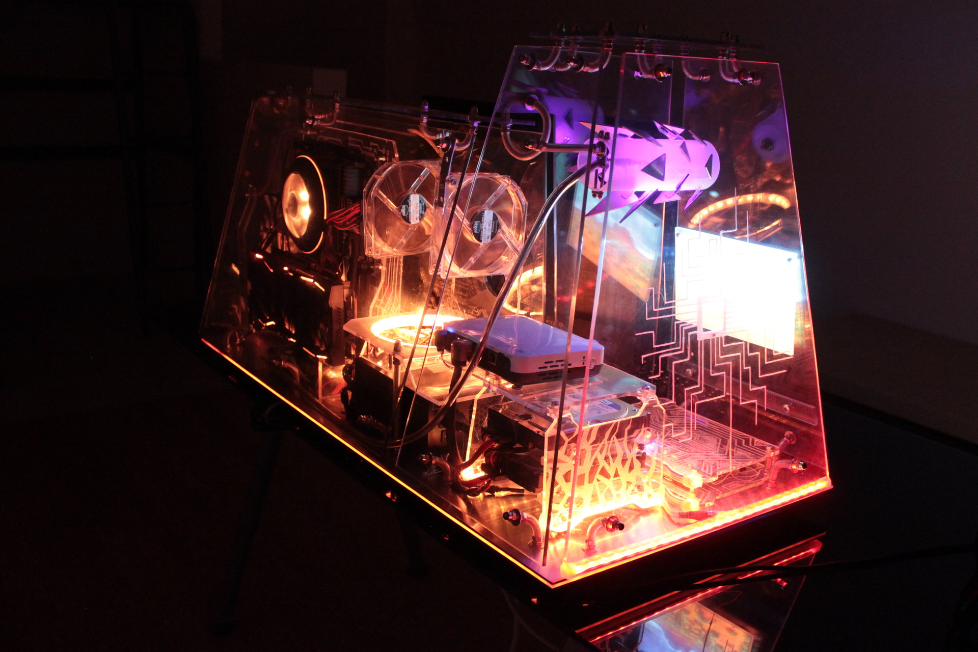
Powered on PC, but with light in the room:
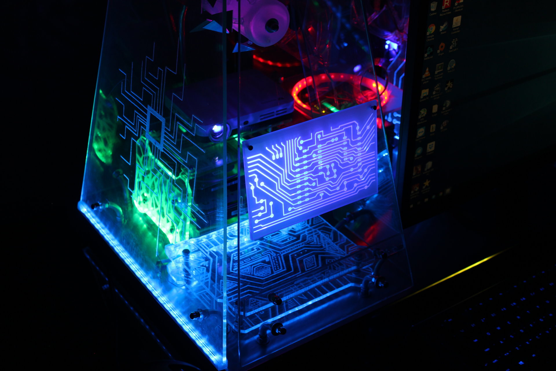
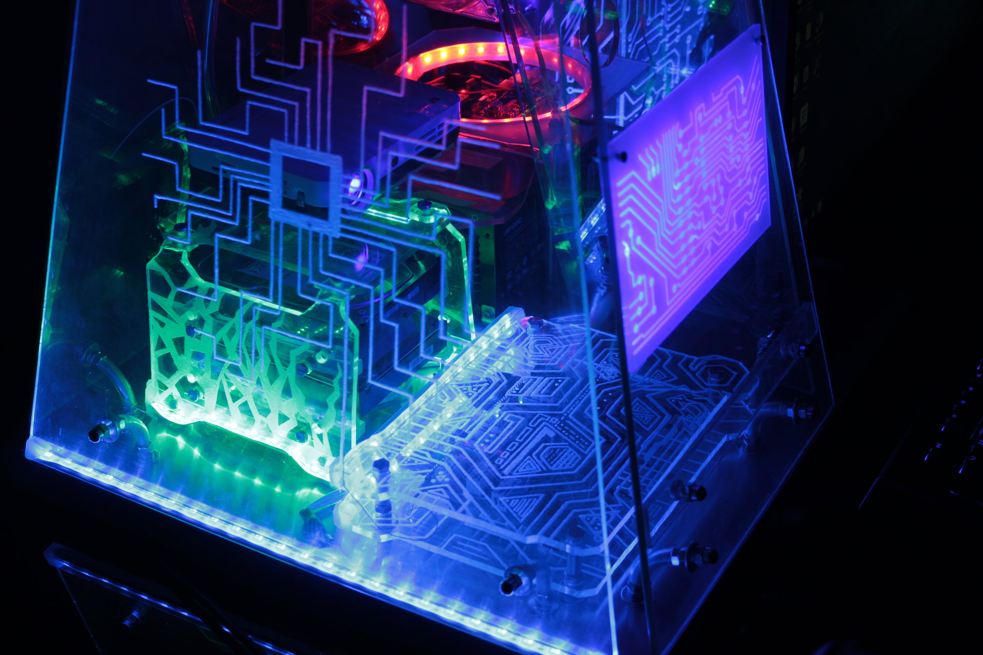
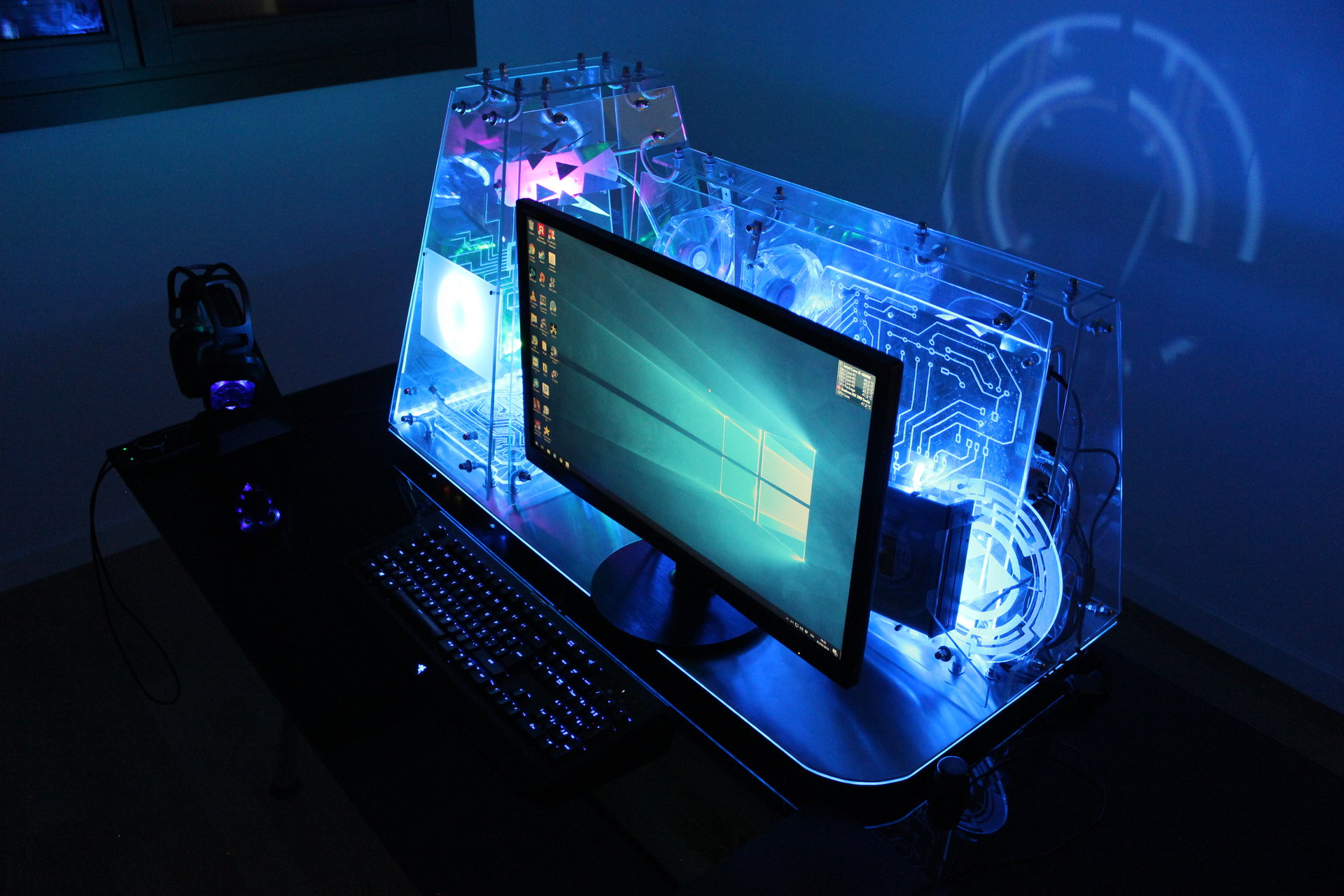
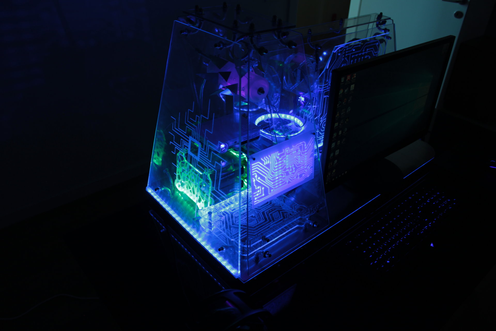
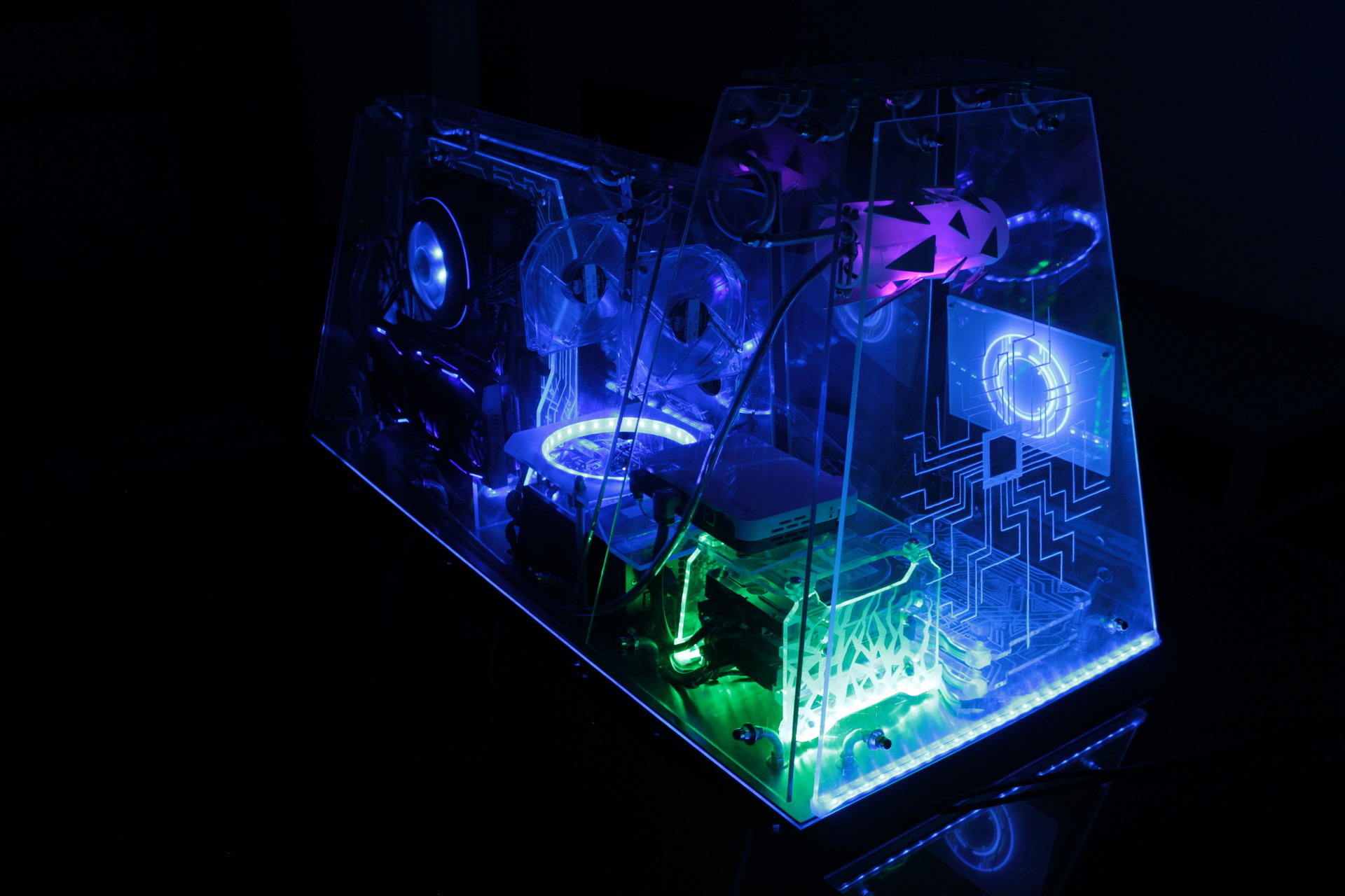
Default state 1:
– mostly blue
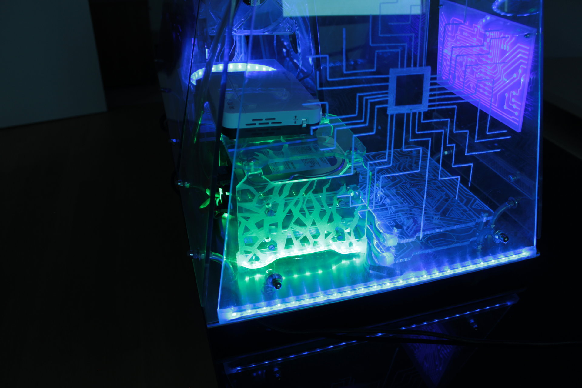
– infection effect that fades from blue to green on the hard disks
– Arduino ring with two rotating red pixel trails
– two yellow pixel trails that run around the base
– projector animation: blue electronic circuit
– proximity sensor “charging” effect: blue->green->yellow->red
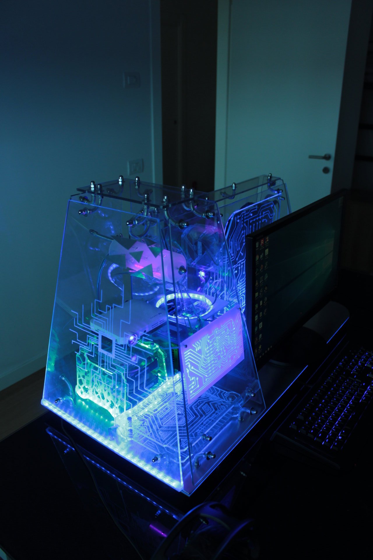
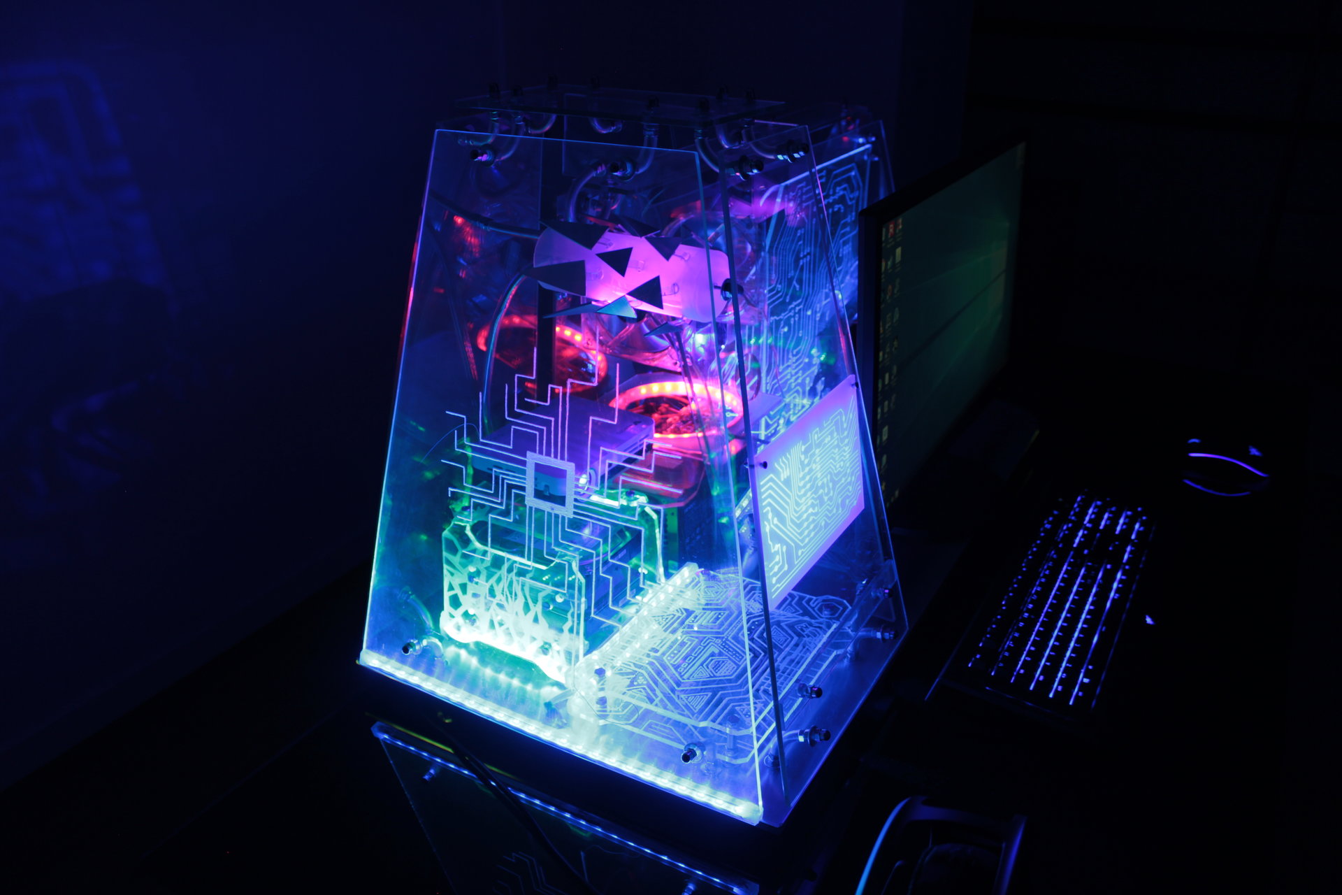
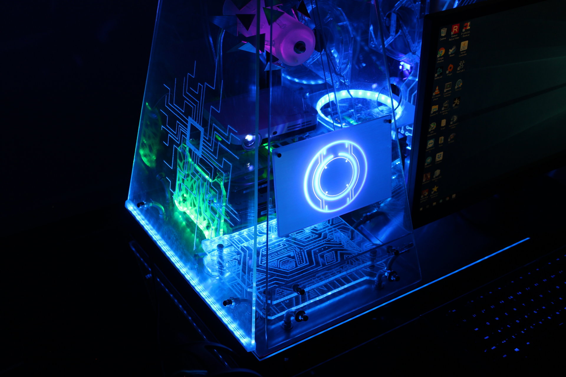
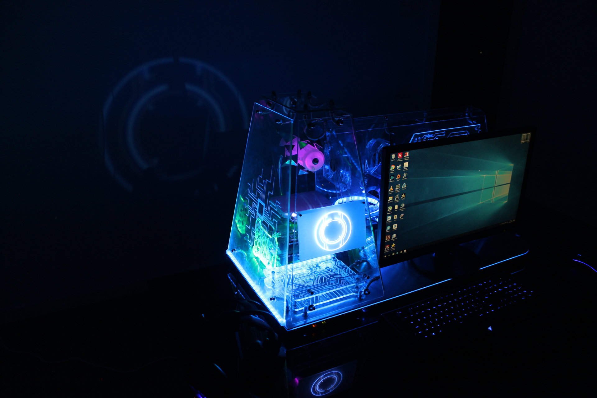
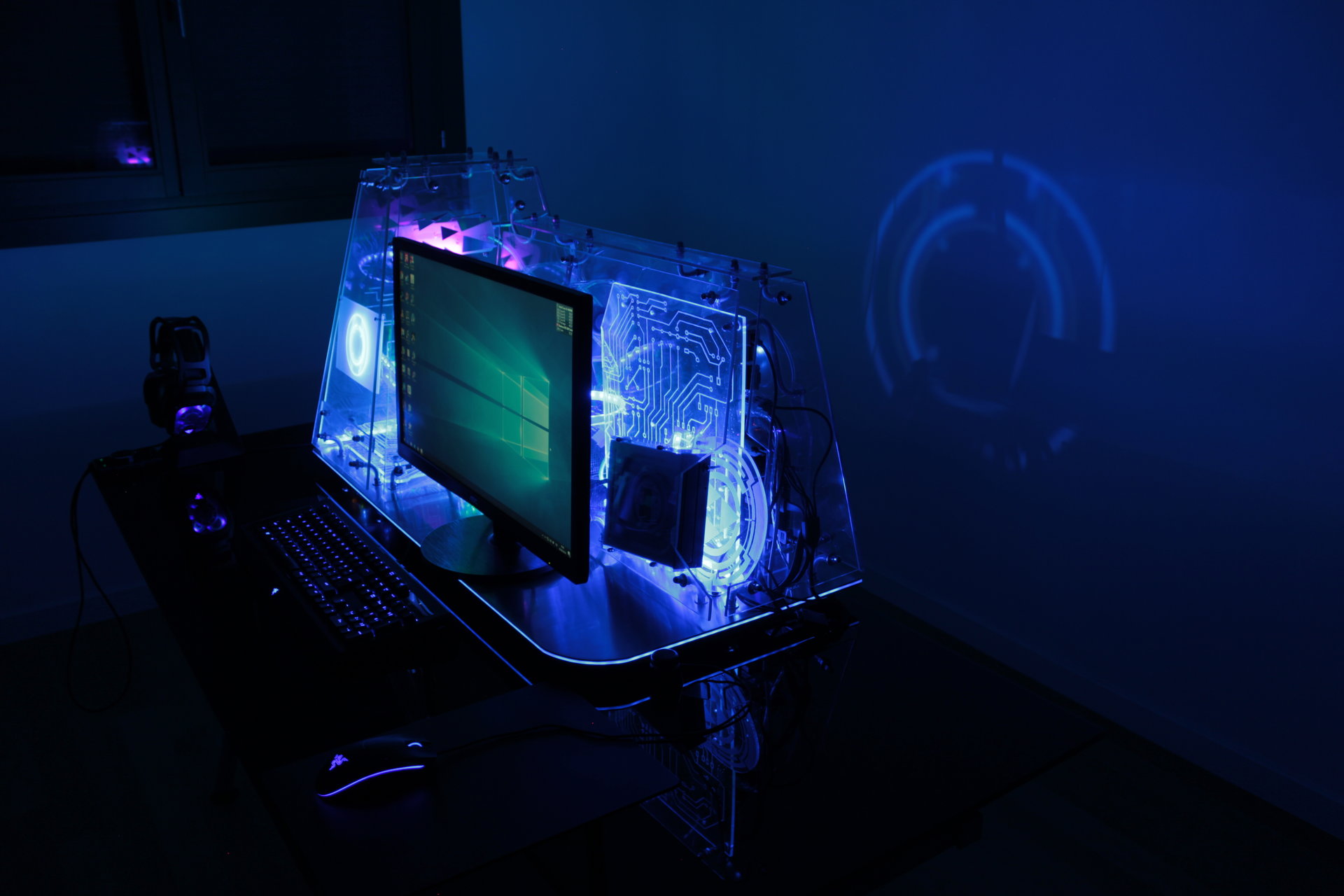
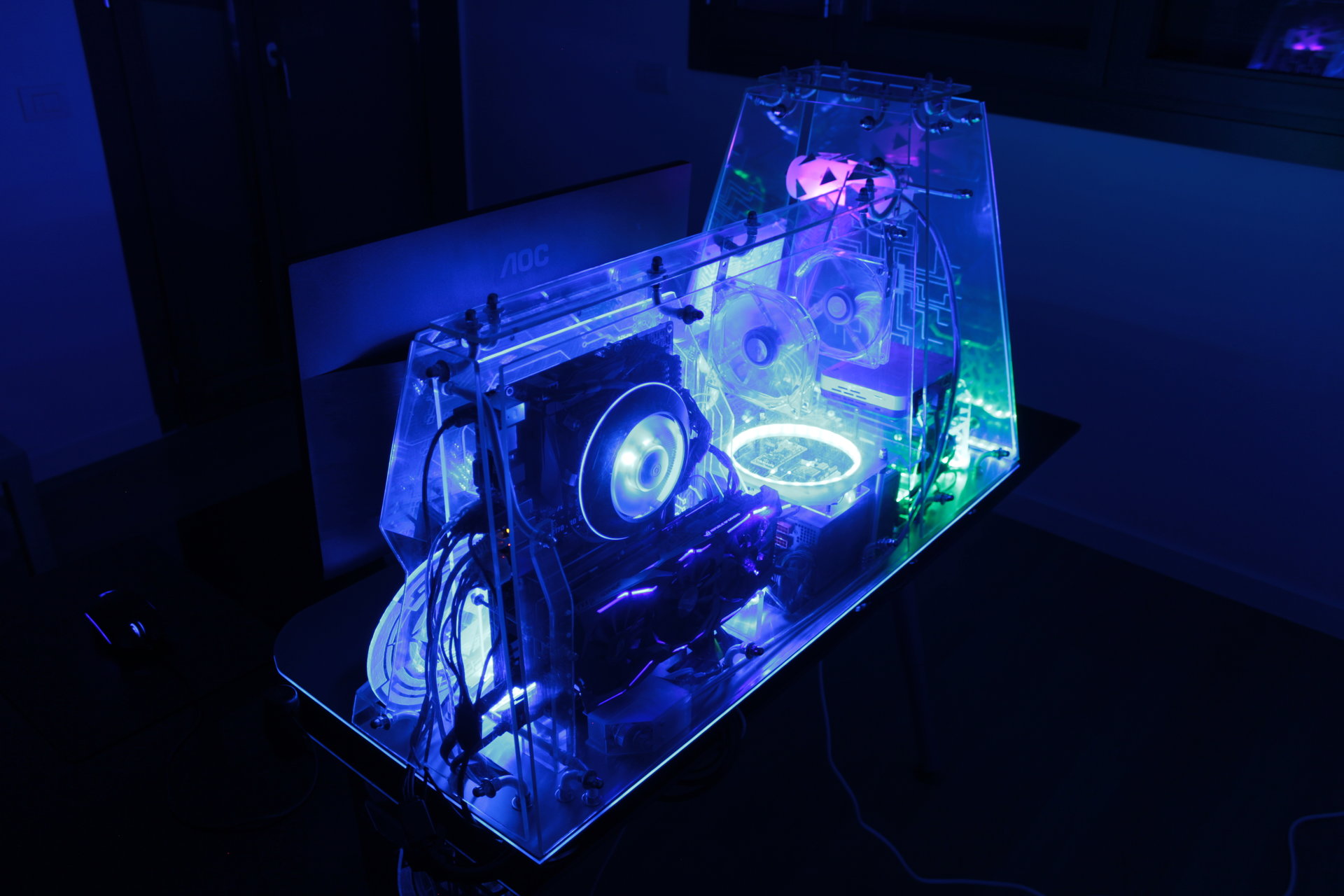
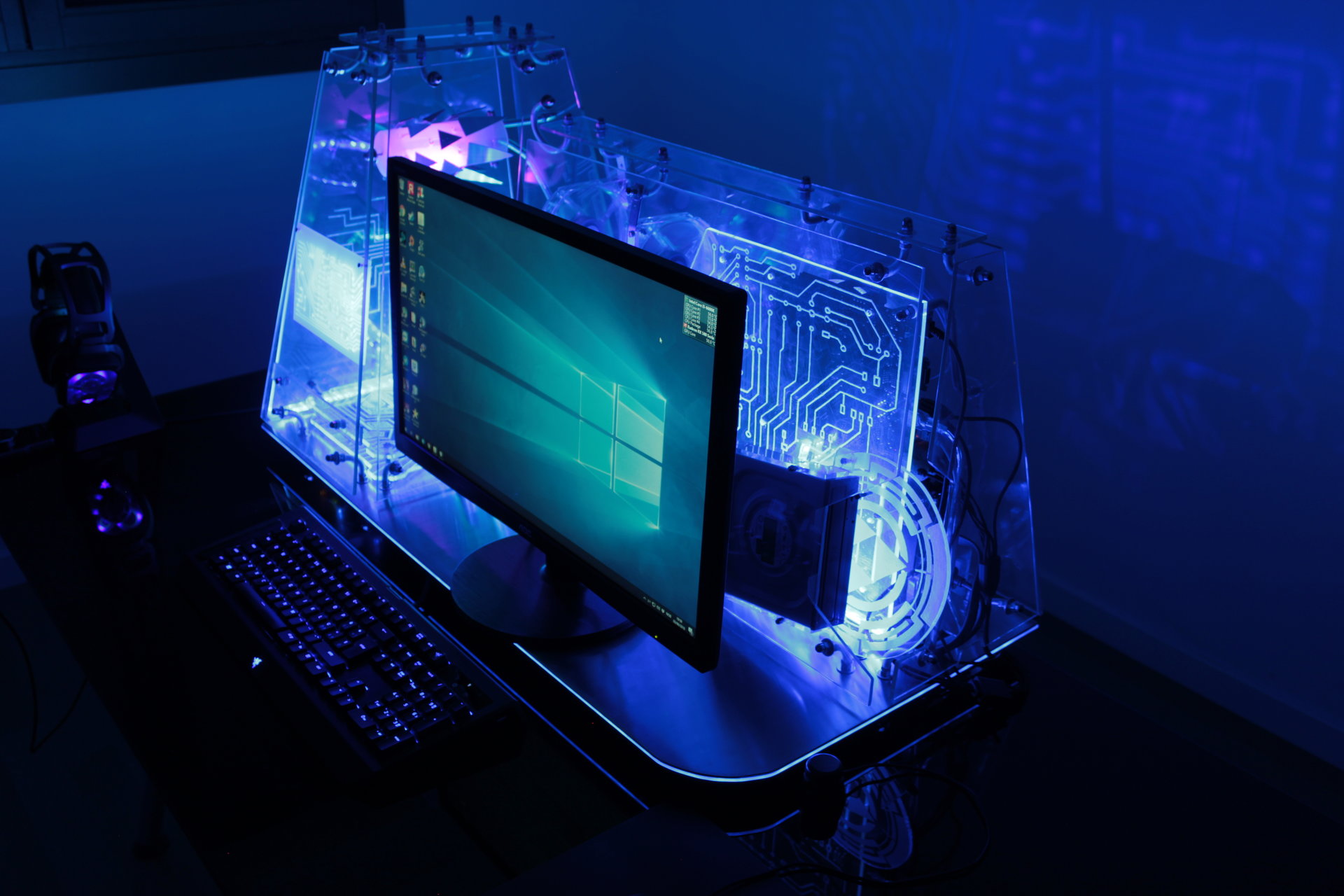
Default state 2:
– mostly blue
– infection effect that fades from blue to green on the hard disks
– Pulsating blue Arduino ring
– Blue base perimeter
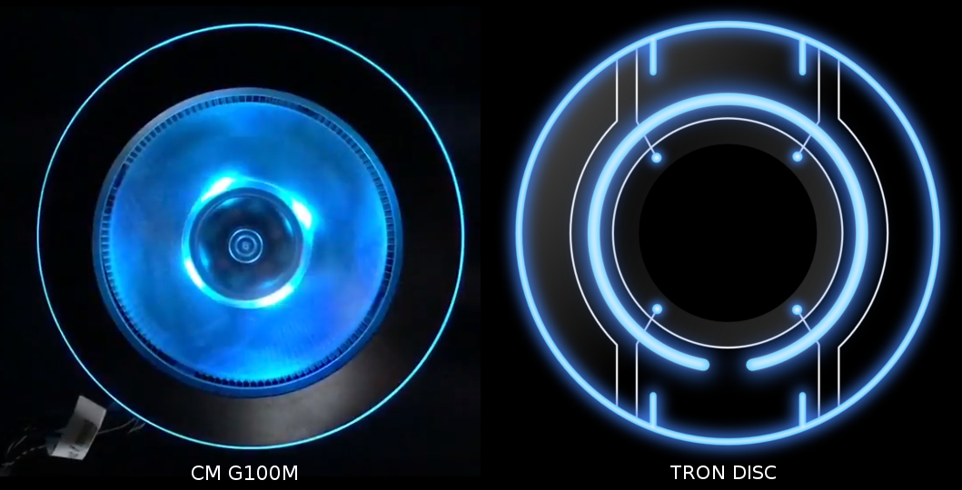
– projector animation: Tron disc
– proximity sensor “charging” effect: blue->green->yellow->red
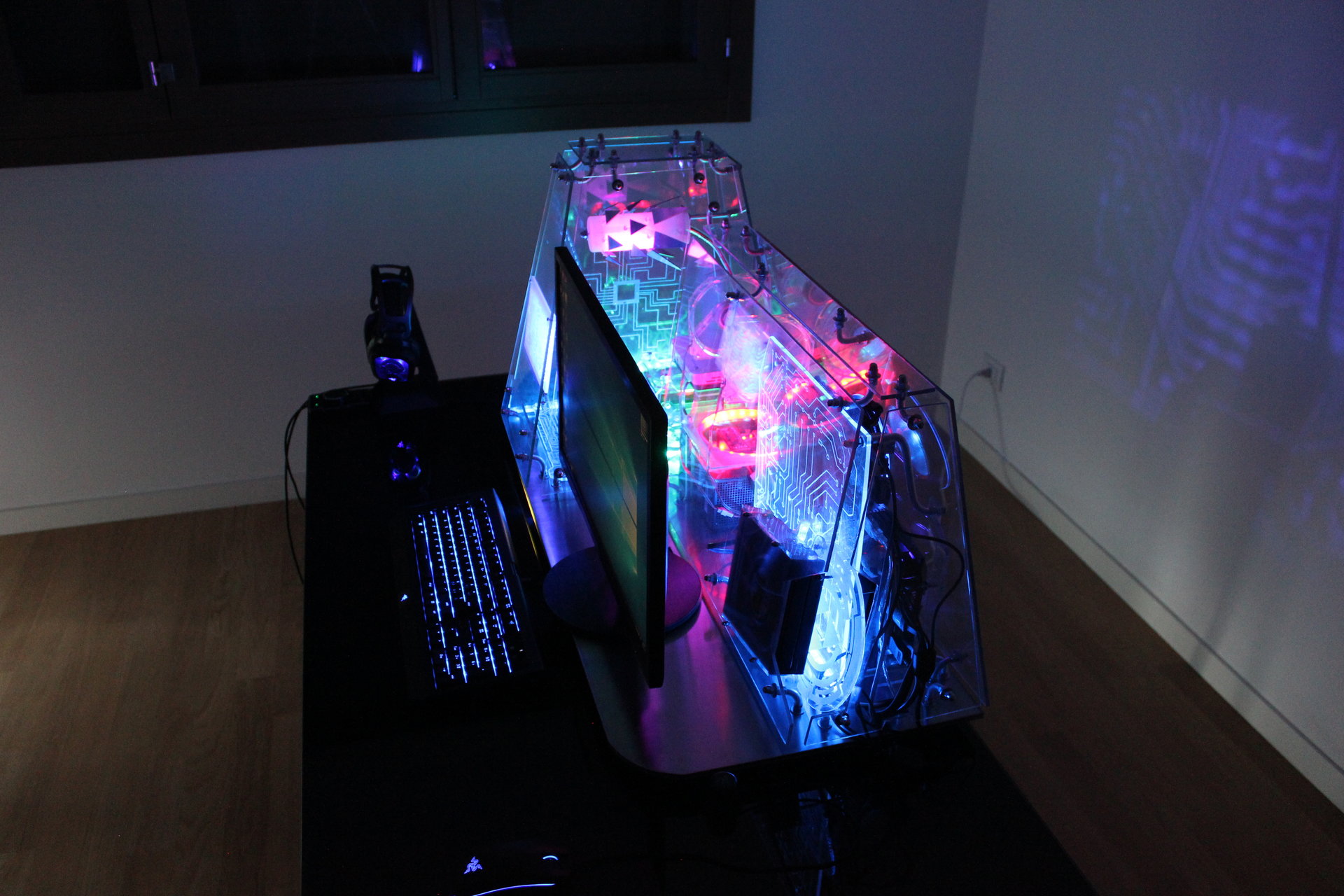
In this state I like the reflection of the projected Tron disc on the room’s wall behind the case (and the disc is animated, in the video it can be seen in movement).
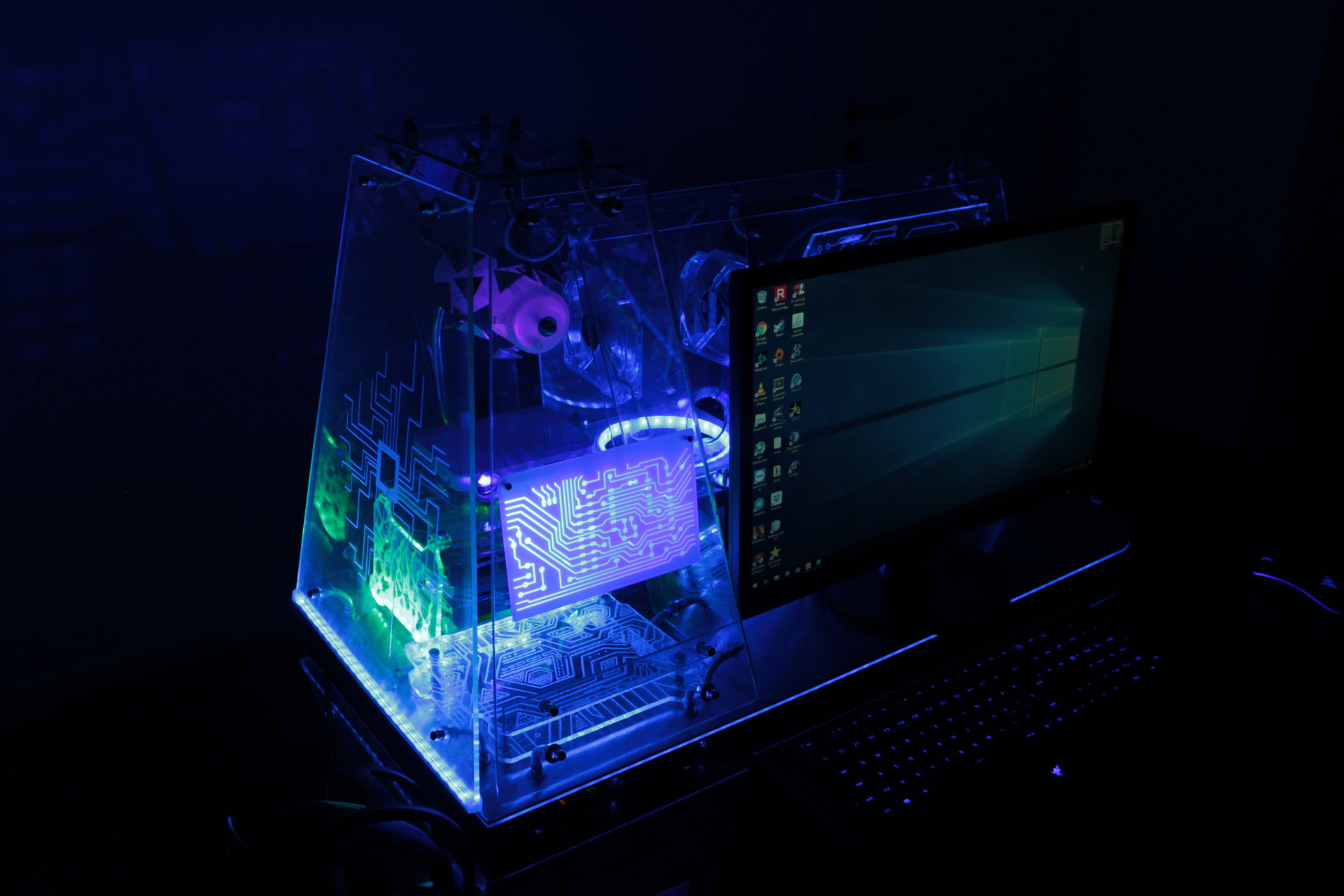
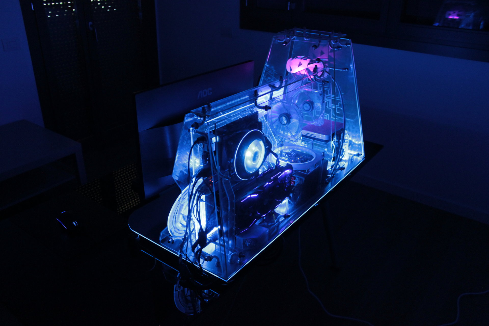
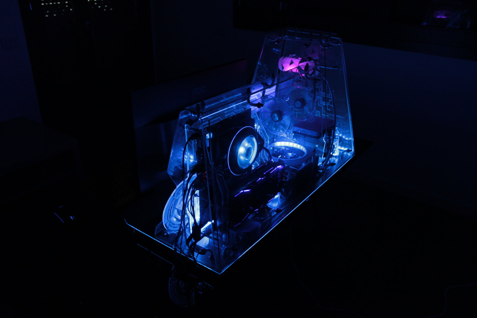
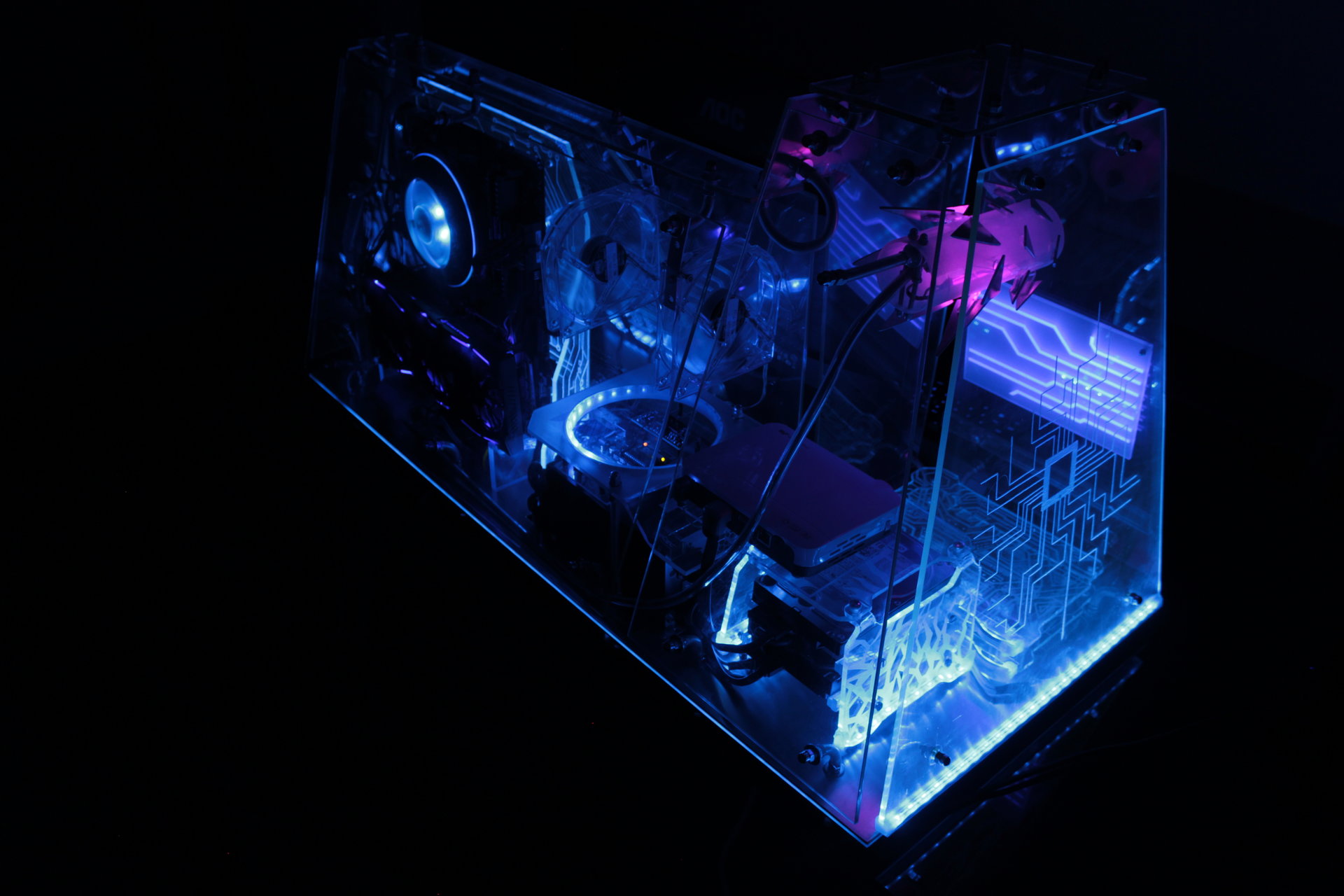
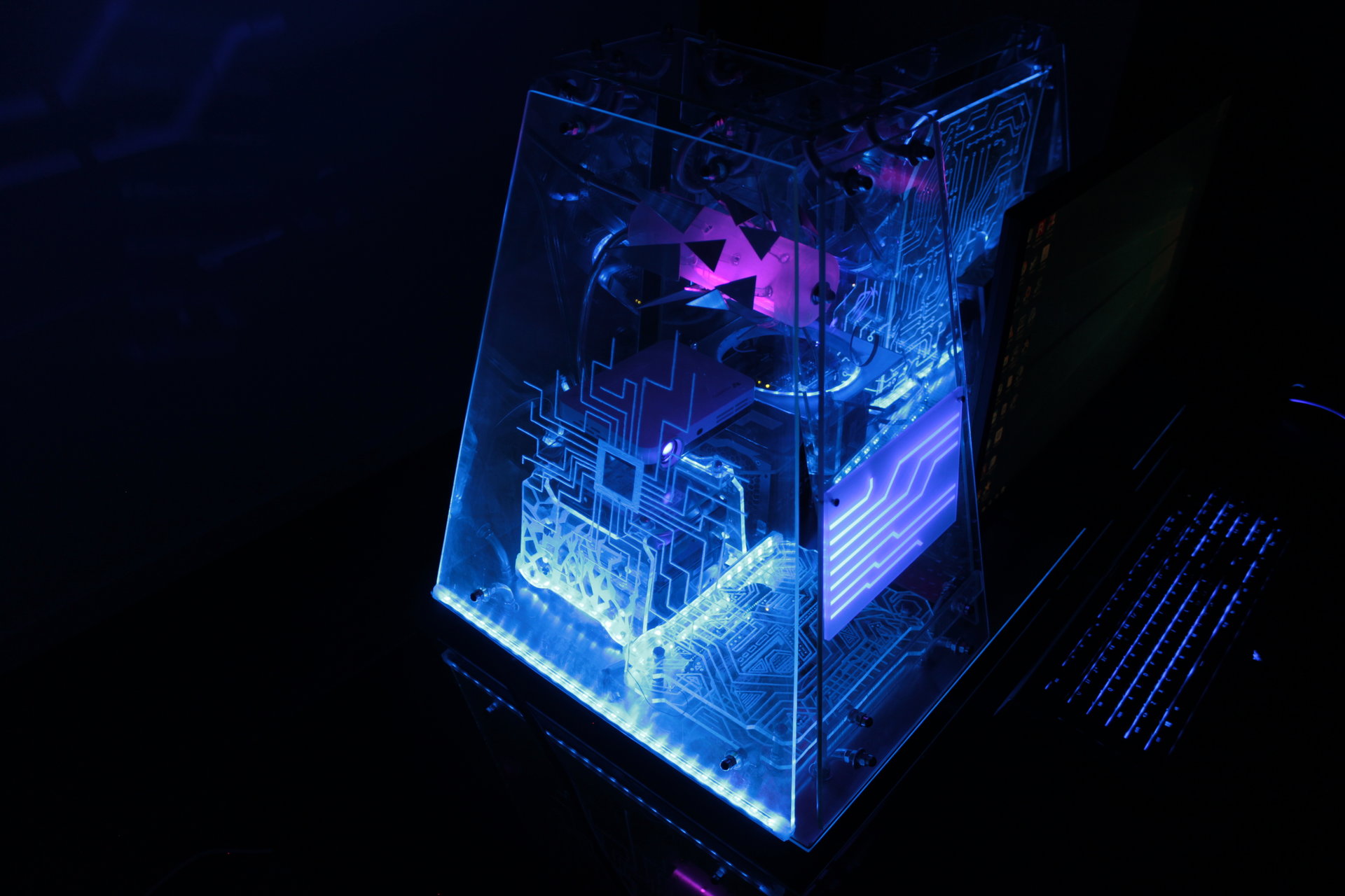
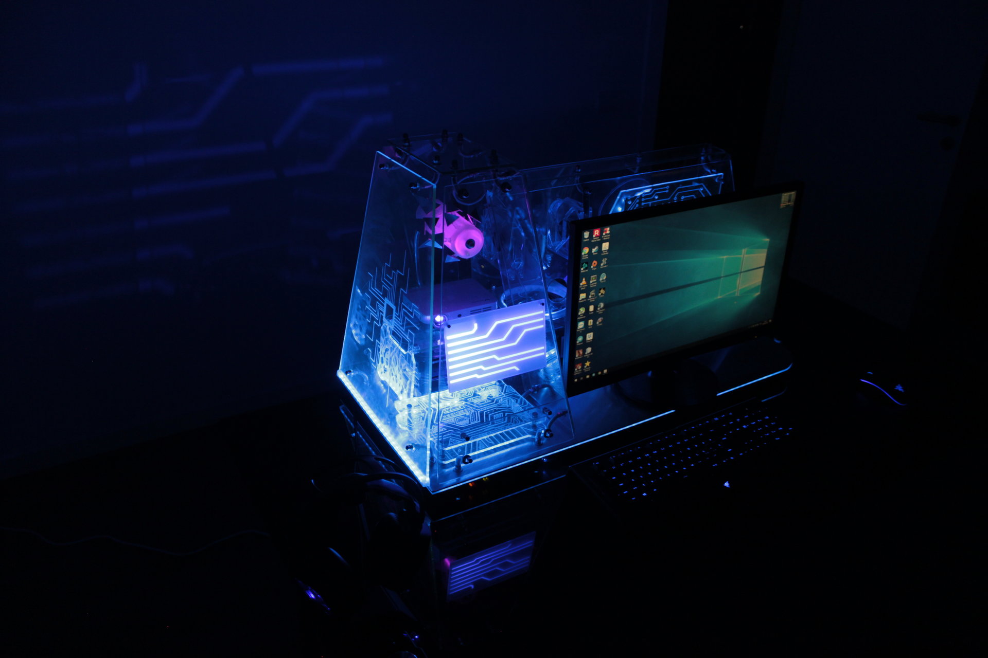
Blue state:
– all blue
– projector animation: Tron themed lines
– proximity sensor “charging” effect: blue->green->yellow->red
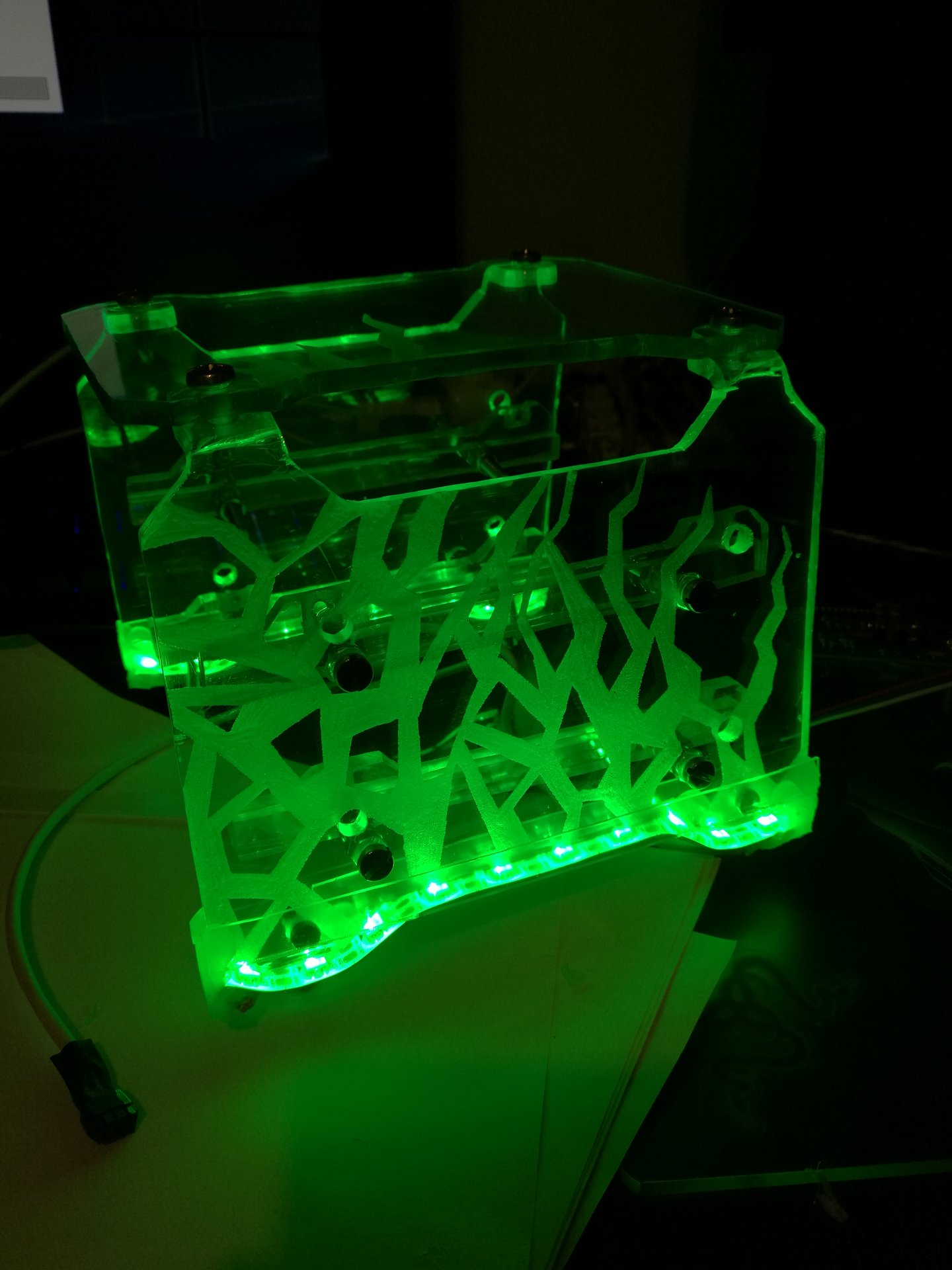
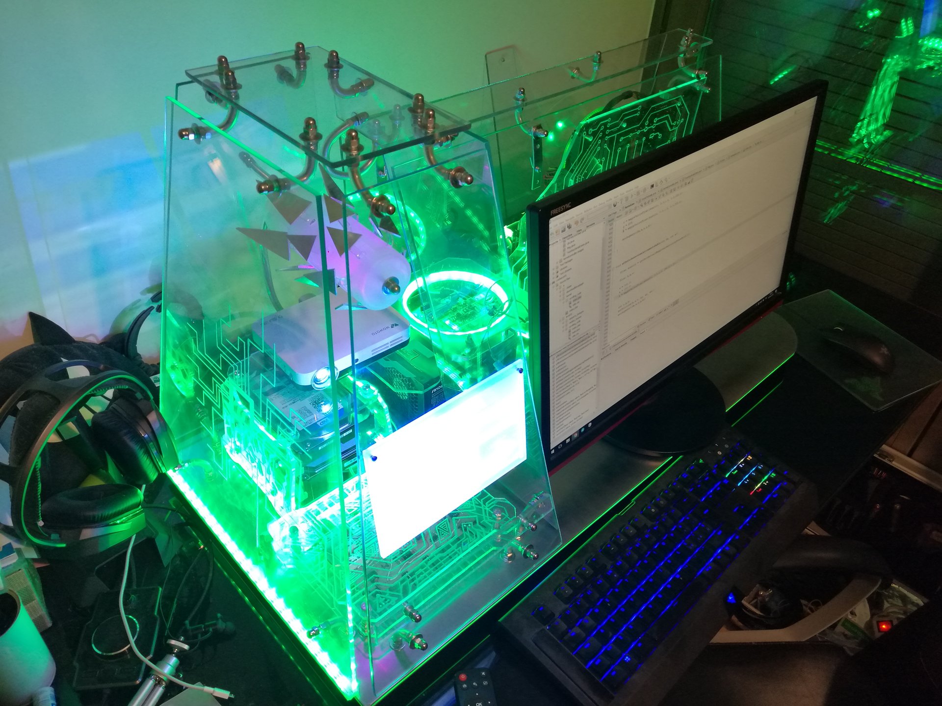
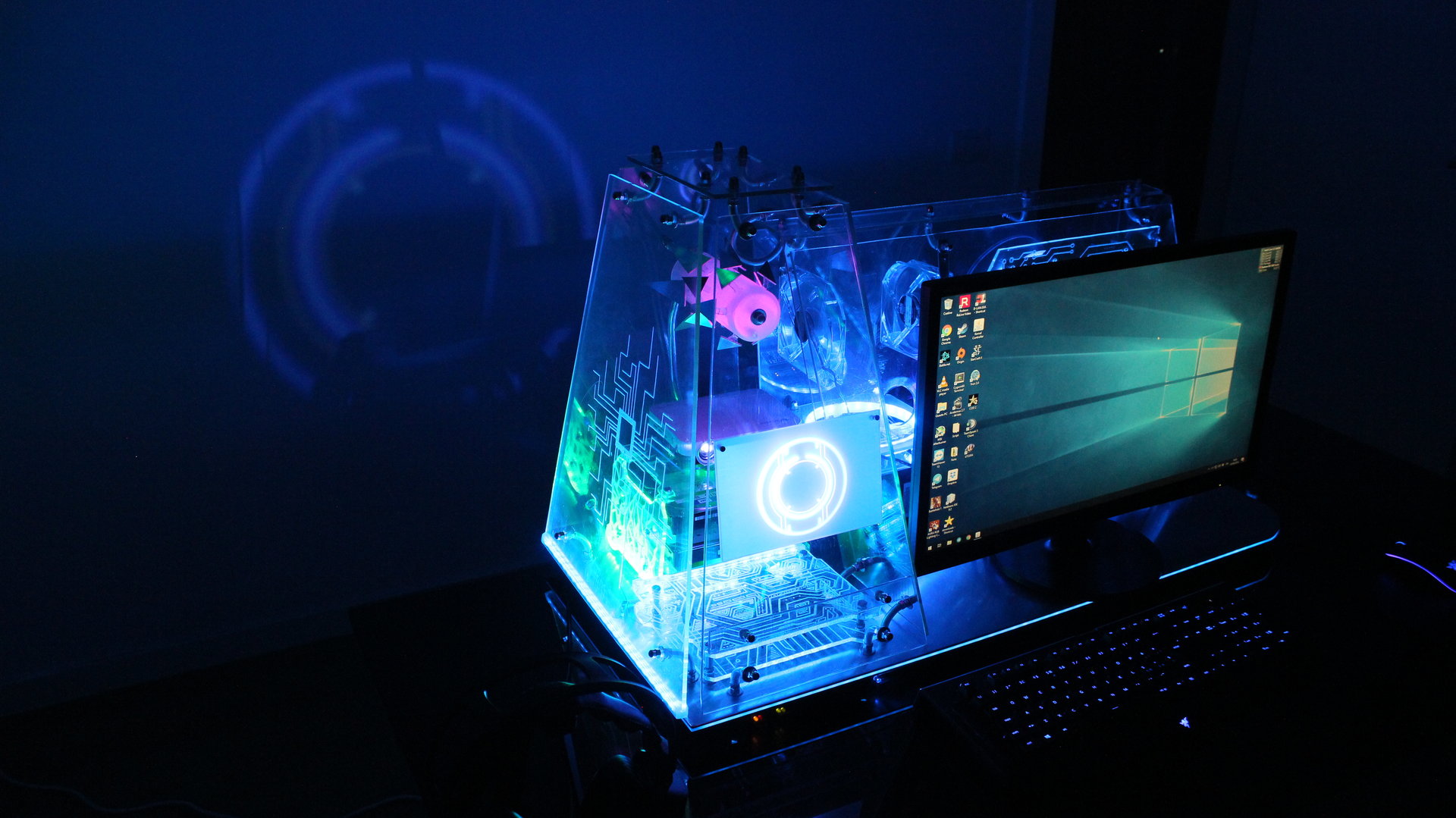
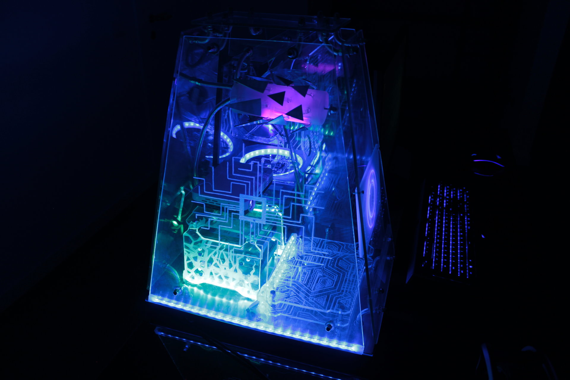
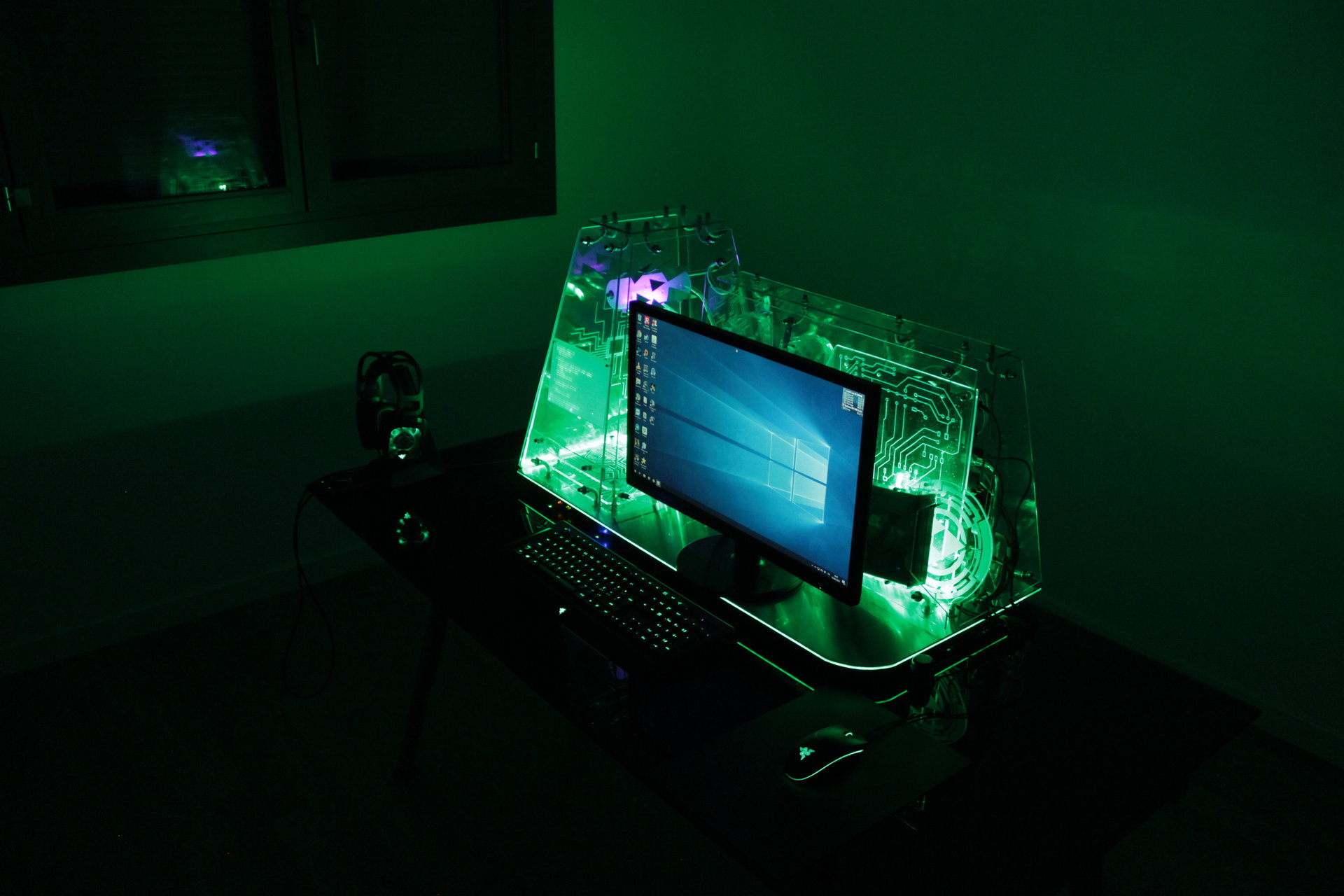
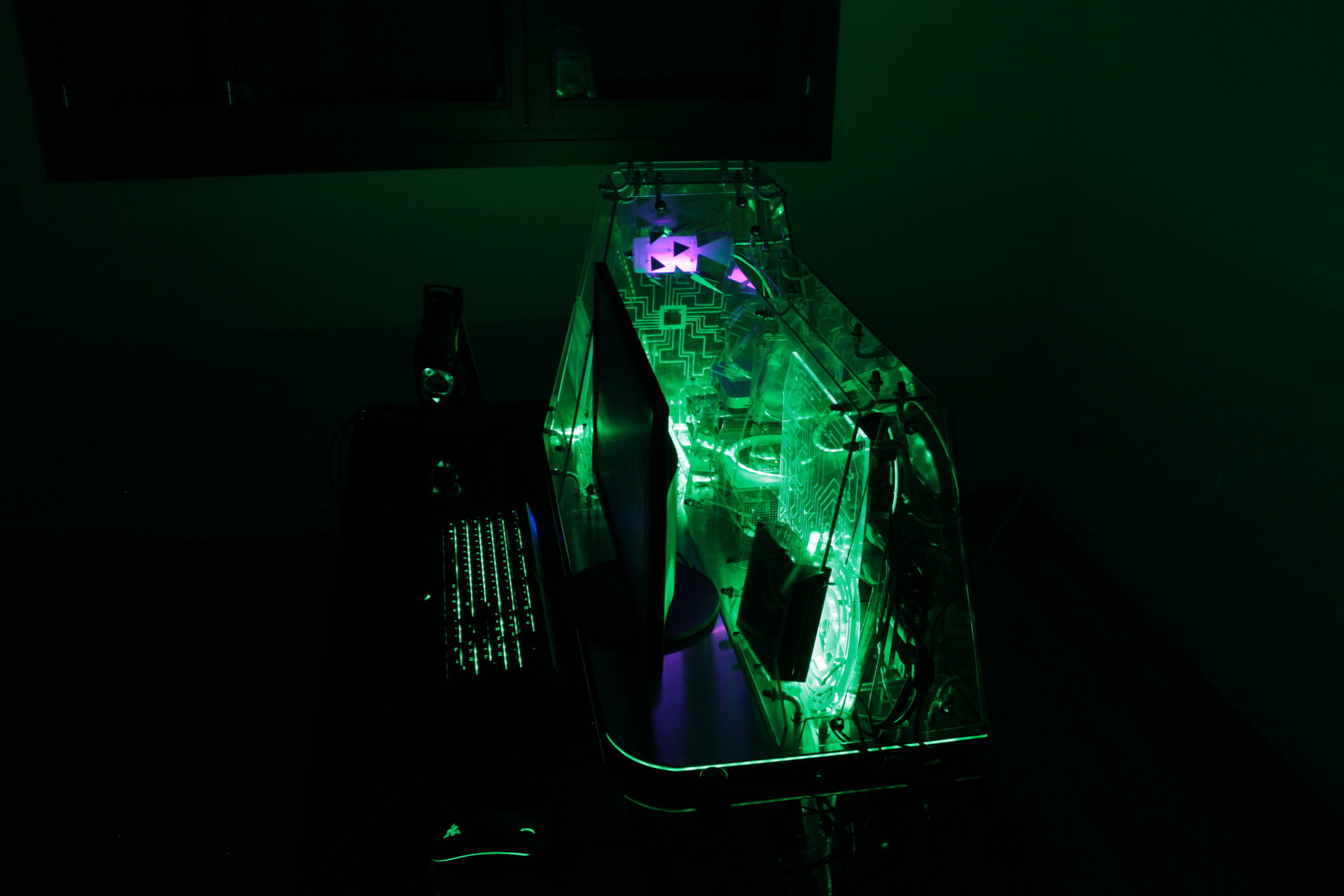
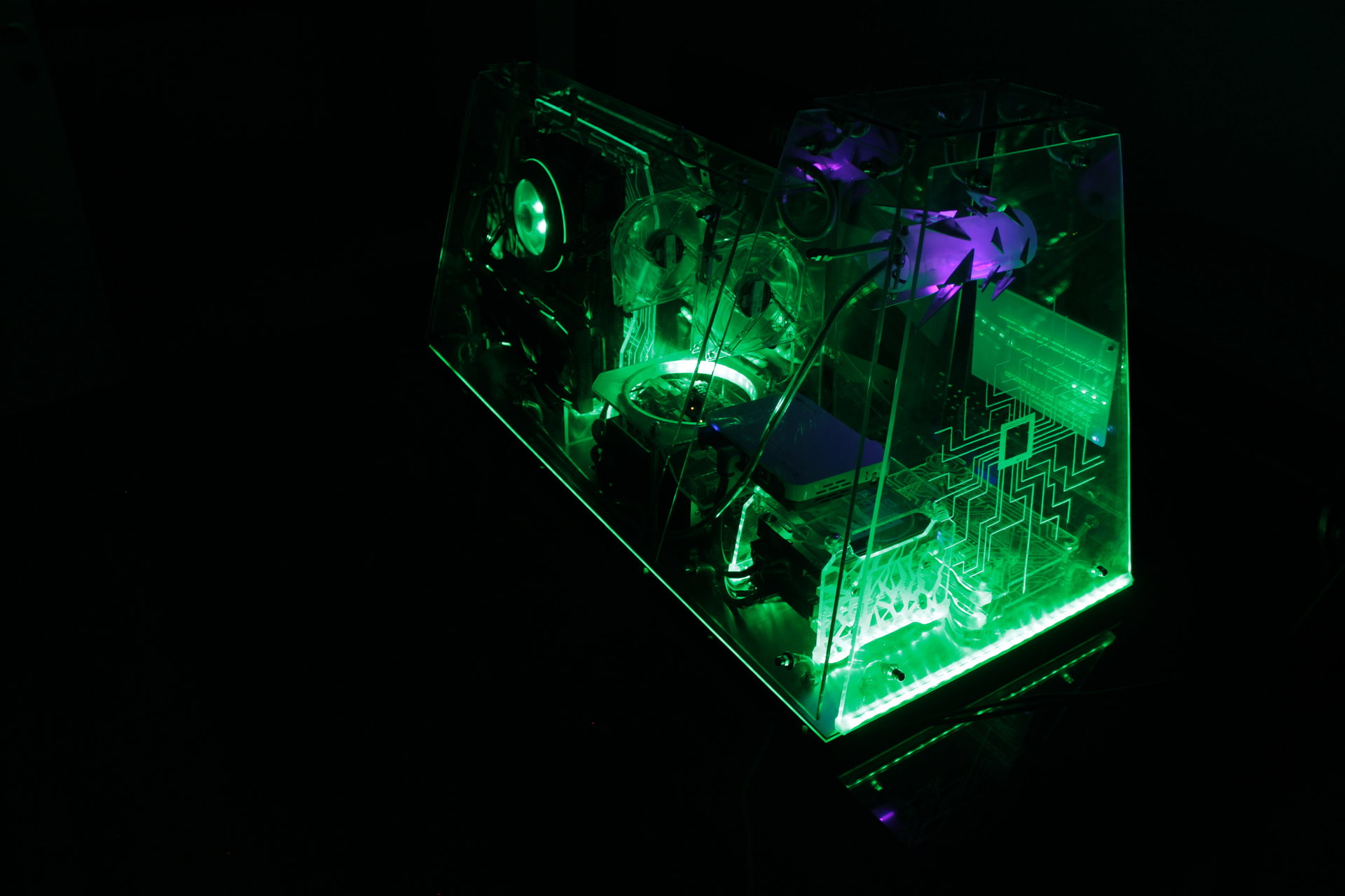
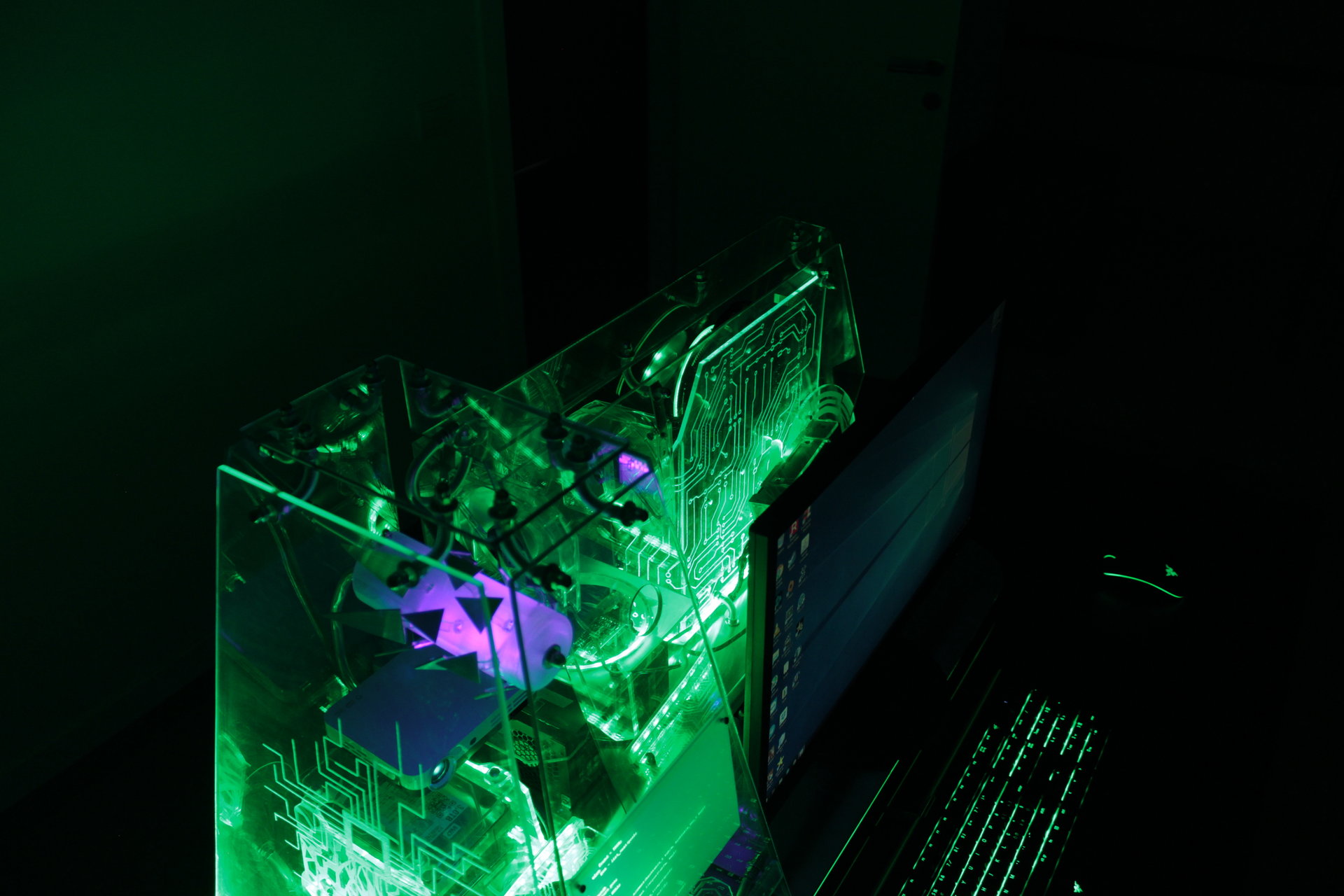
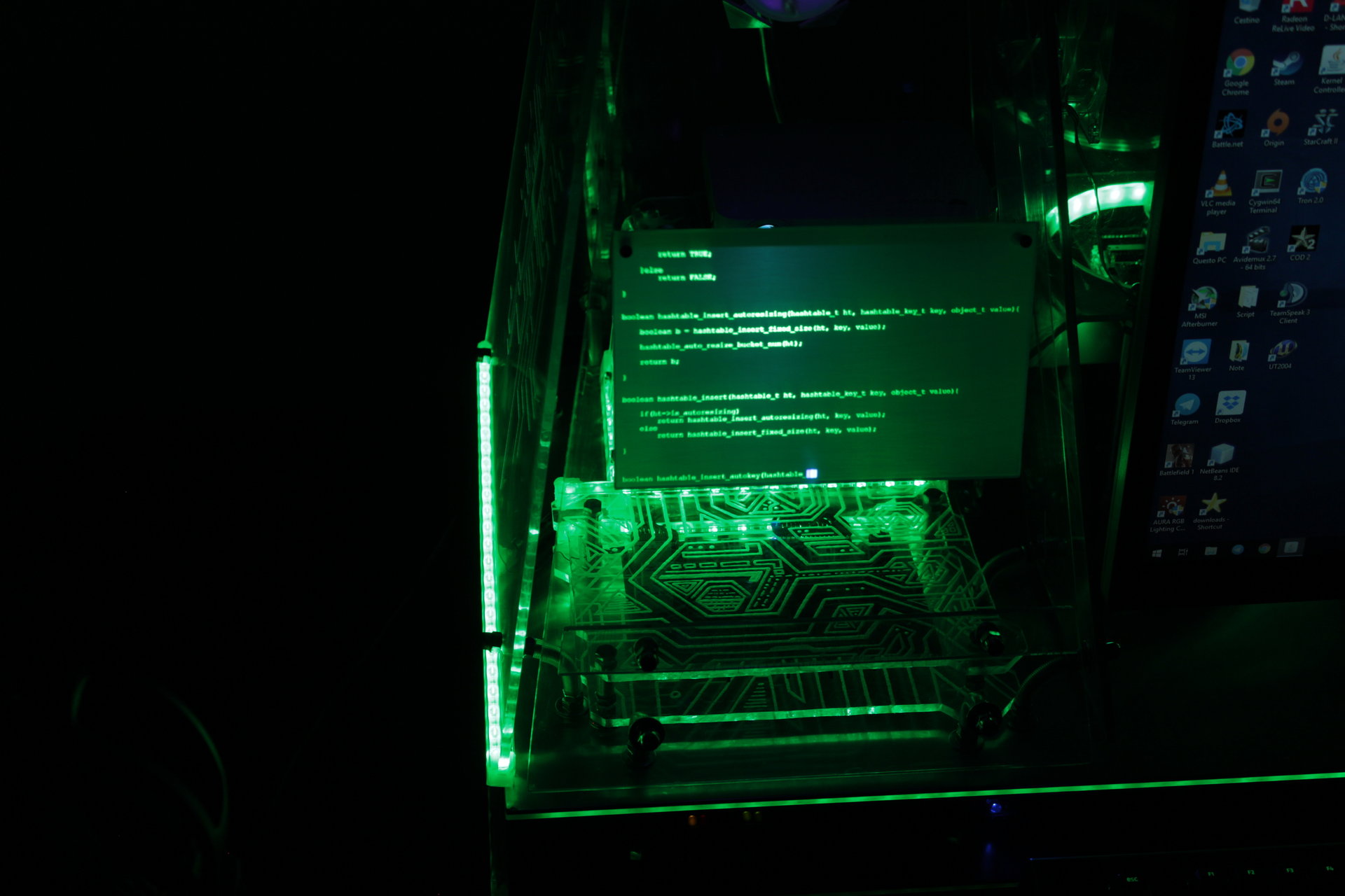
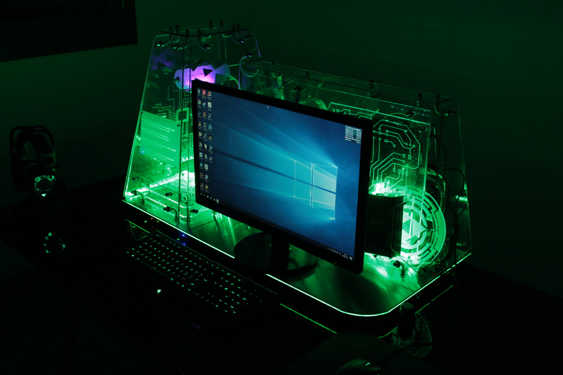
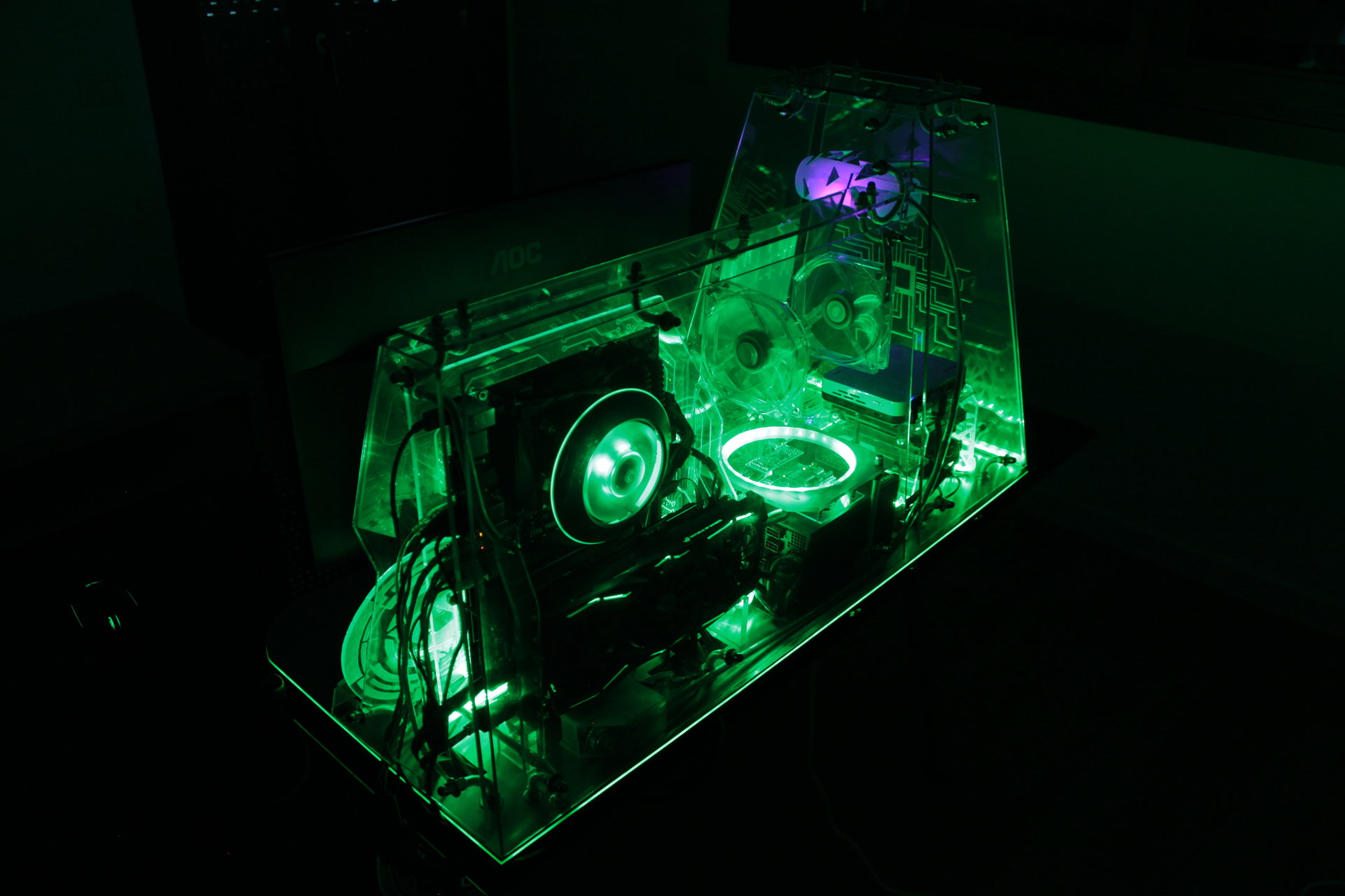
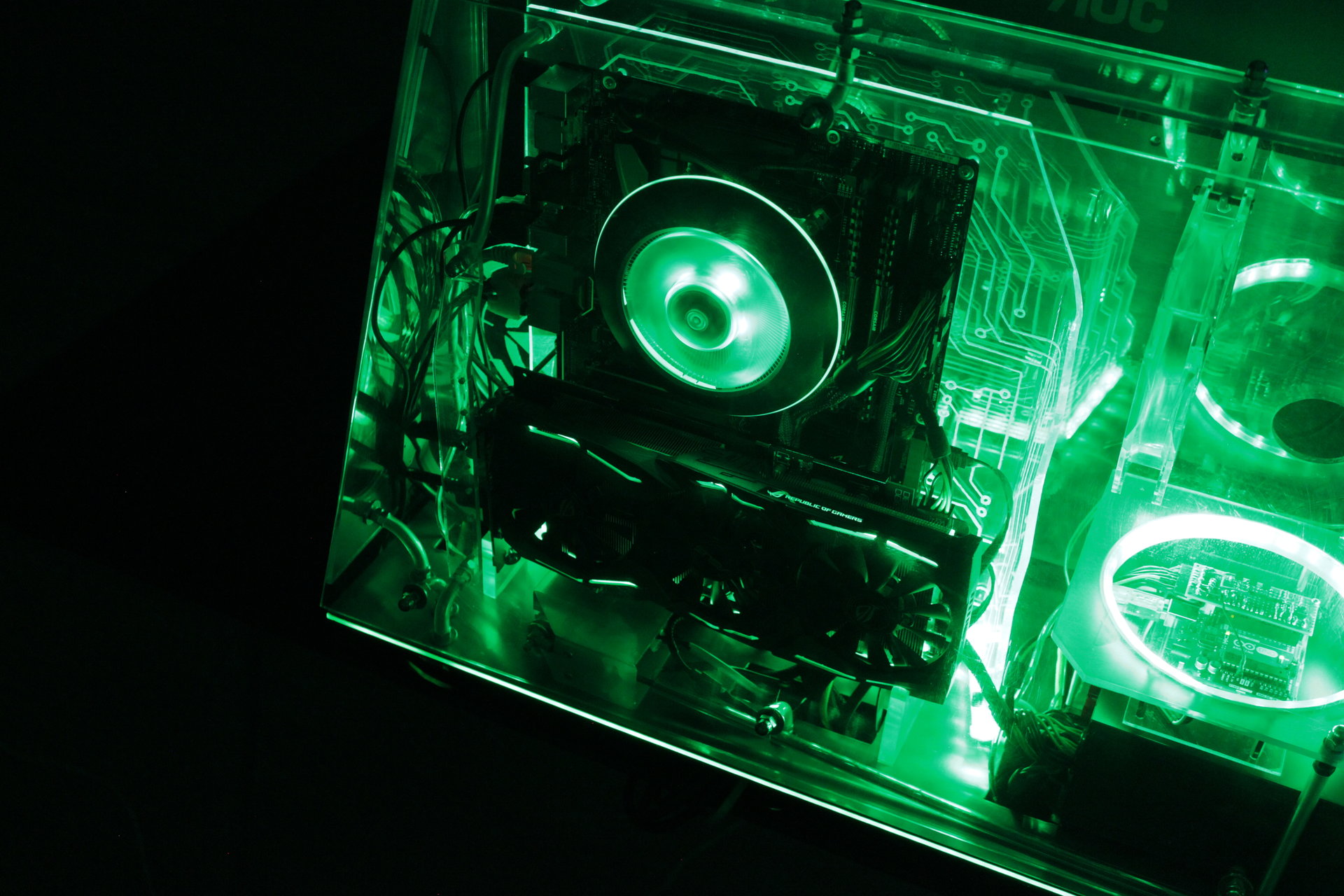
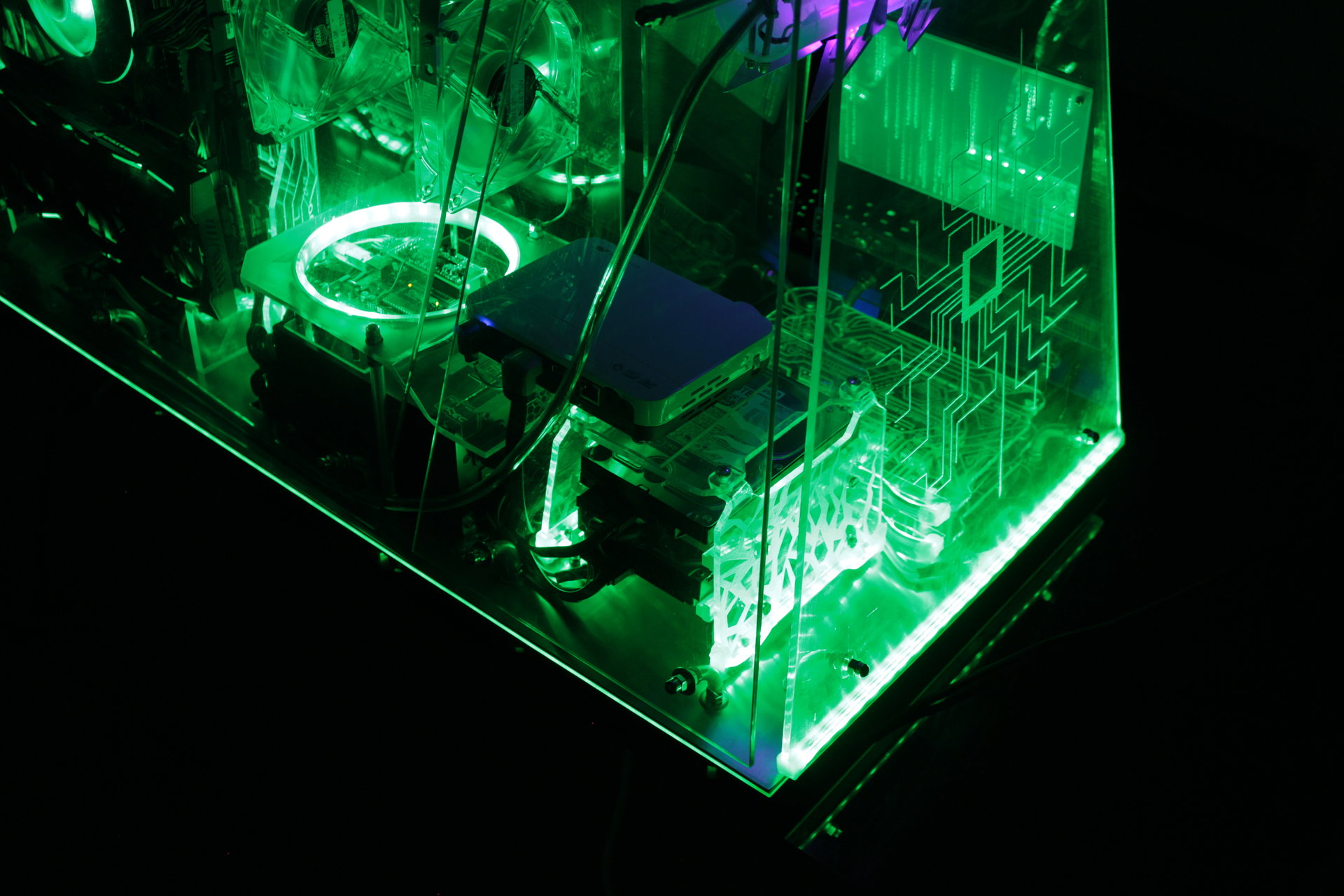
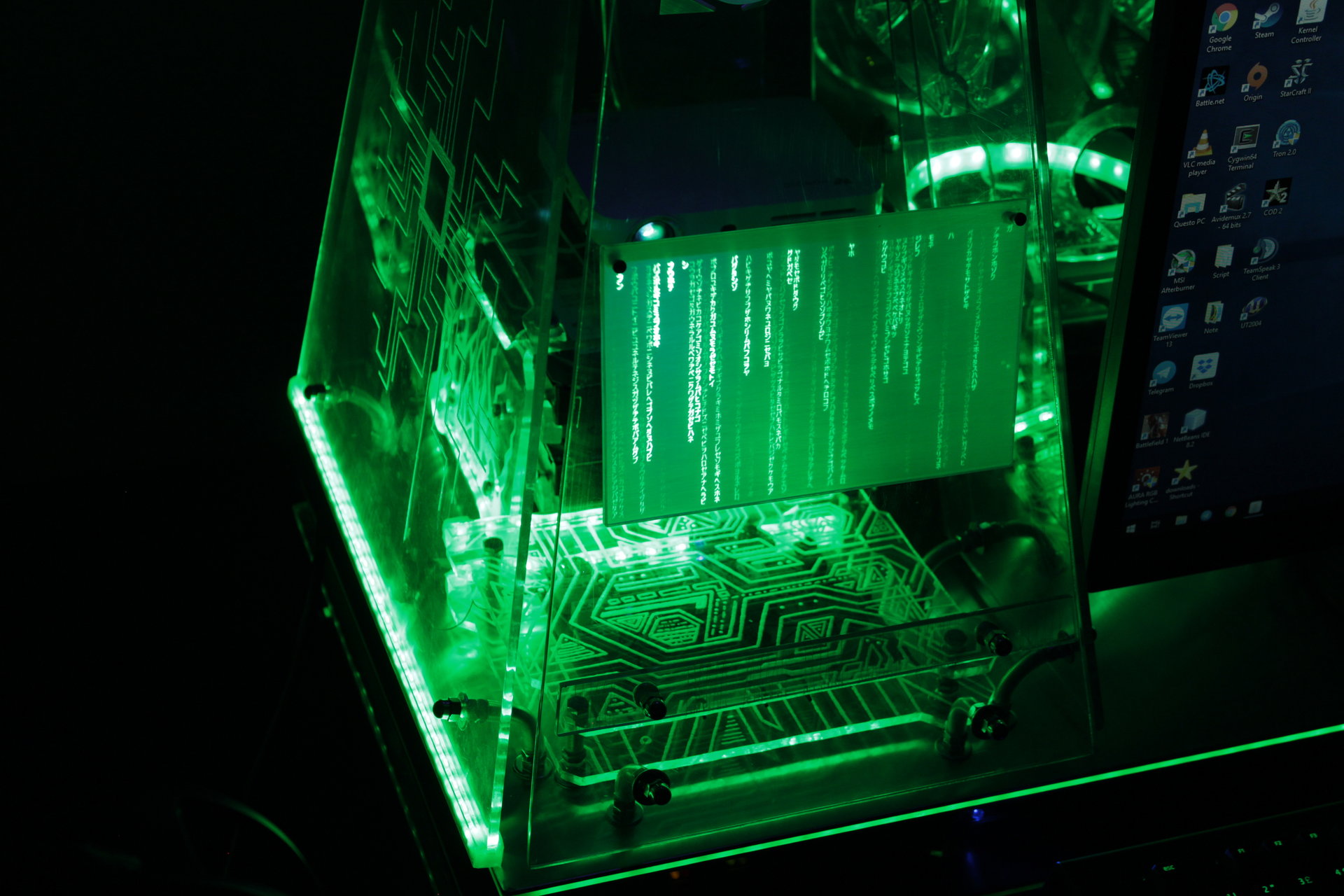
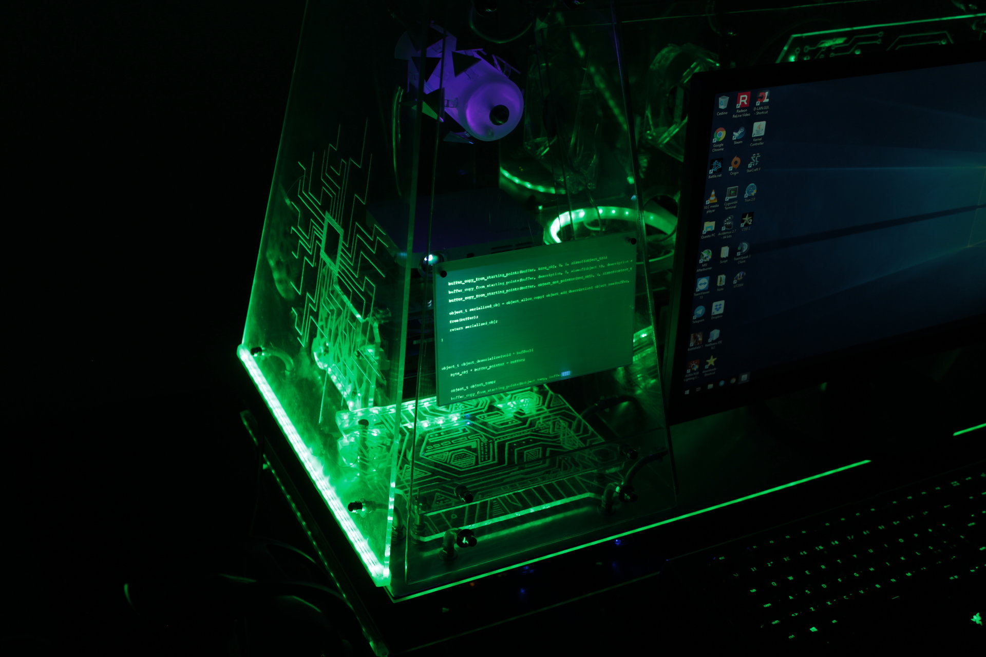
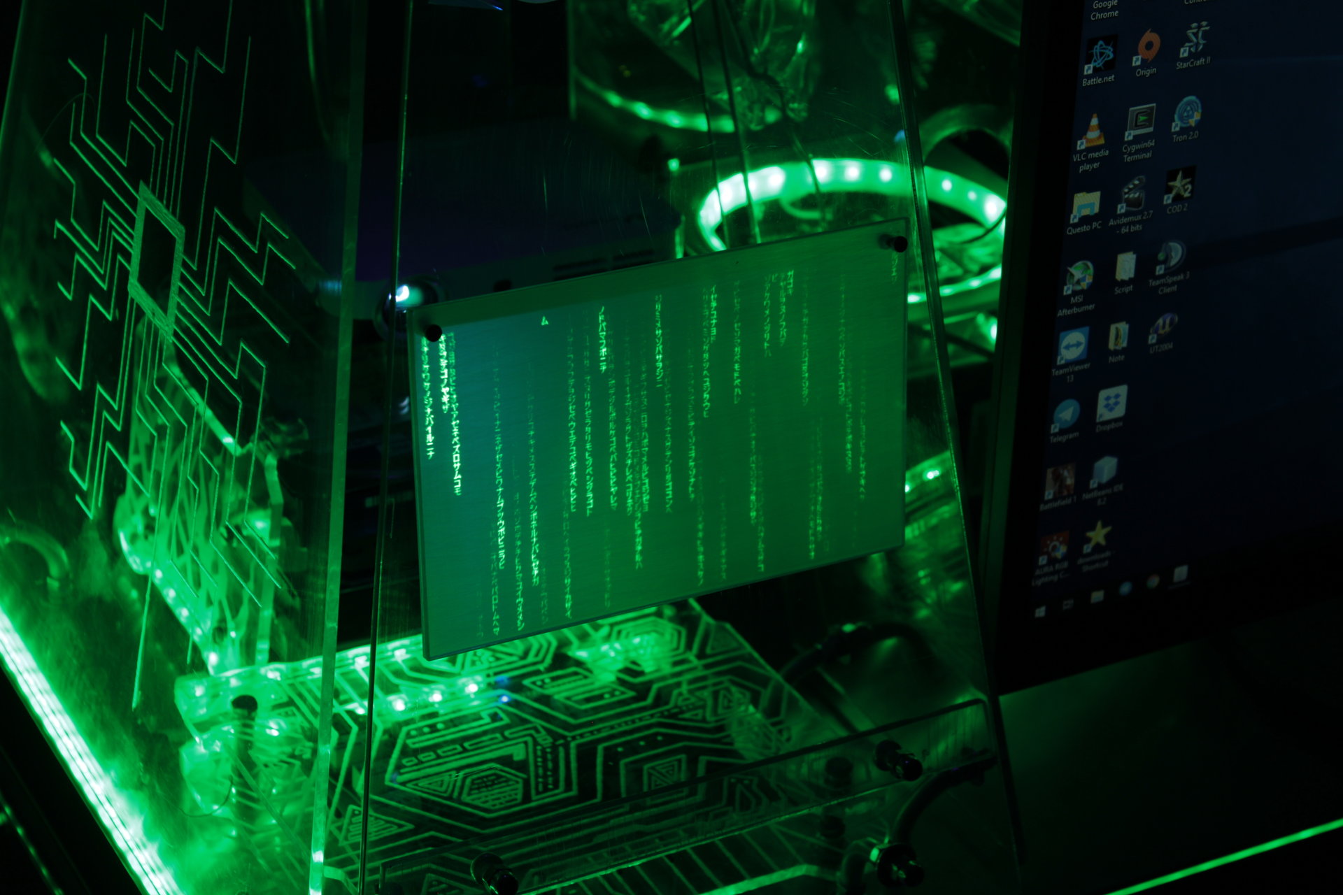
Green states:
– all green
– Arduino ring with 1-3 rotating green pixel trails
– projector animation: scrolling code, or Matrix-style falling code
– proximity sensor “charging” effect: green->white
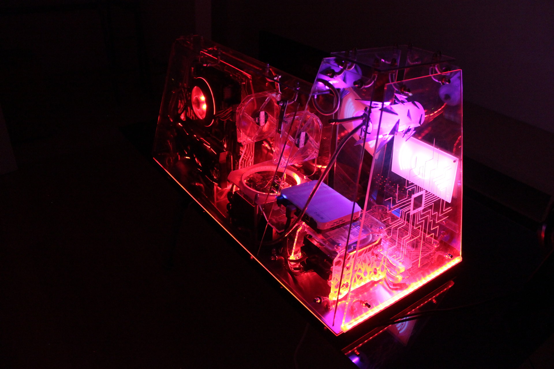
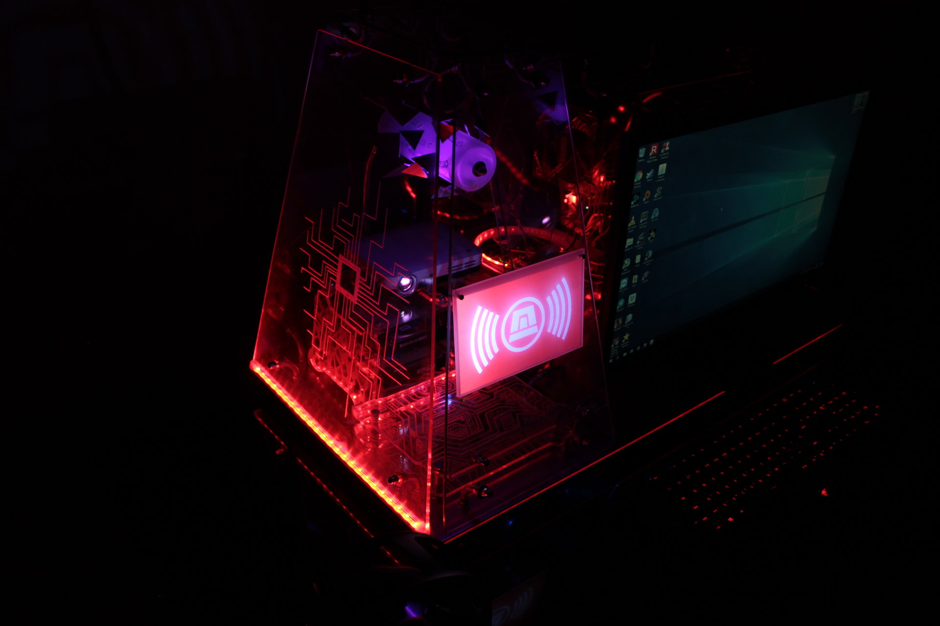
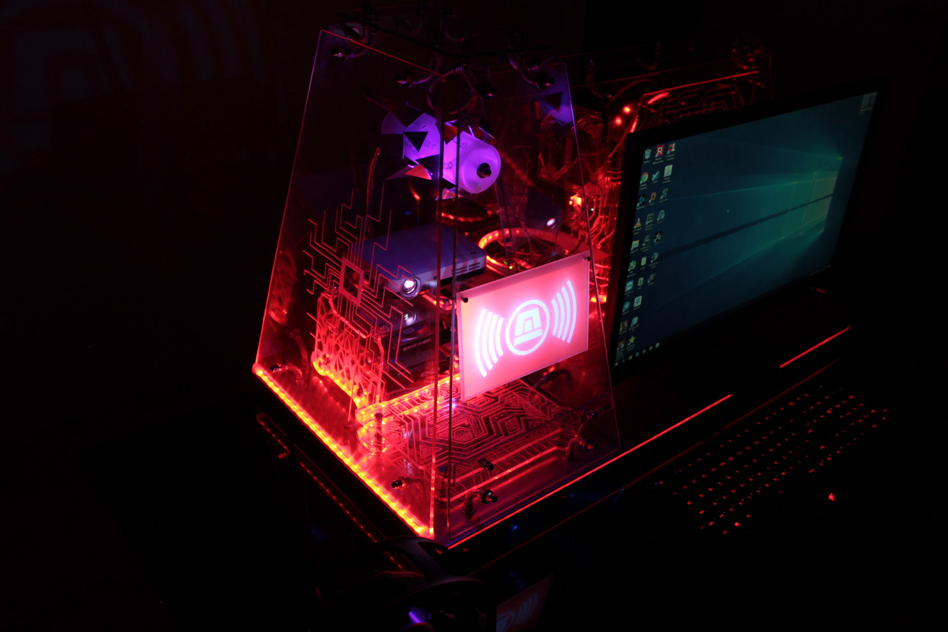
Red state:
– all pulsating red (alarm-style)
– Arduino ring with 1 rotating red pixel trail, like an alarm signal
– projector animation: flashing red alarm signal
– proximity sensor “charging” effect: “incandescent” effect, red->yellow->white
Desert state:
– all orange
– projector animation: desert with rolling tumbleweeds 😀
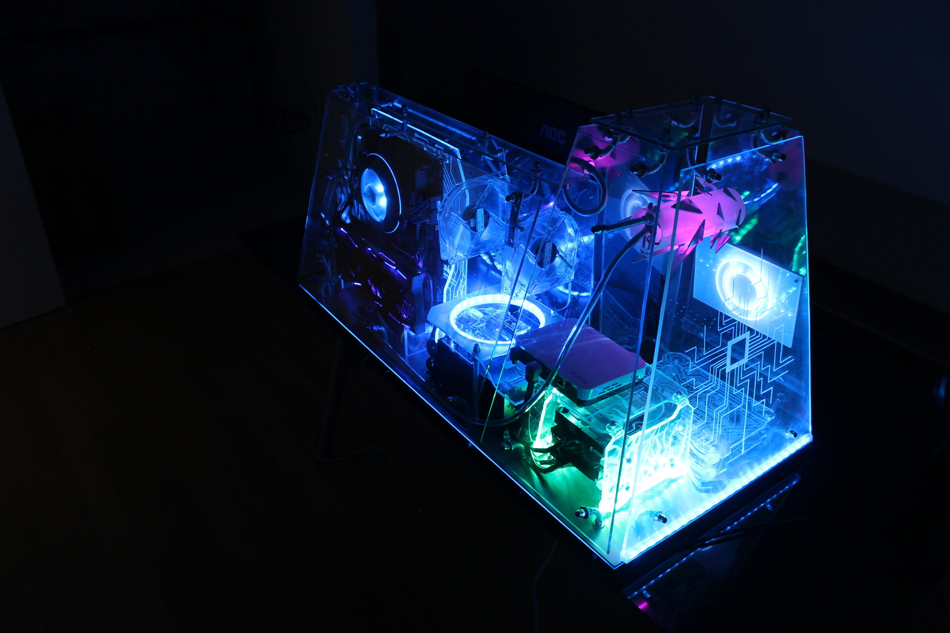
Colourful states:
– lighting with constant fluid color hue cycling on all the led strips
Questo sito usa i cookie per offrirti la migliore esperienza possibile.
Procedendo con la navigazione sul sito o scrollando la pagina, accetti implicitamente l'utilizzo dei cookie sul tuo dispositivo. Informativa sull'utilizzo dei cookieAccetto